PC817 Optocoupler with a Raspberry Pi Pico
The PC817 is a 4-pin optocoupler that passes a signal through light across 5 kV of isolation, so a 12 V or 24 V circuit can talk to a microcontroller safely.
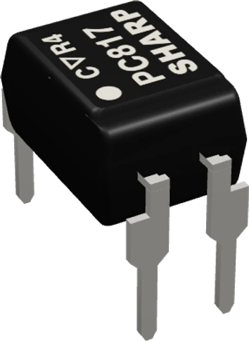
On the Raspberry Pi Pico the PC817's LED is lit from GP0 through 1 kOhm and its phototransistor is read on GP1 with the RP2040's internal pull-up. The isolation is the point: in a real build the LED side is the outside circuit and only the transistor side meets the Pico's 3.3 V.
Wiring the PC817 Optocoupler to the Raspberry Pi Pico
Pin by pin.
| PC817 Optocoupler | Raspberry Pi Pico | Note |
|---|---|---|
| A | GP0 | through a 1 kΩ resistor |
| K | GND | |
| C | GP1 | |
| E | GND |
What to know on the Raspberry Pi Pico
- From GP0 at 3.3 V through 1 kOhm, with the LED's 1.2 V typical forward drop, about 2 mA flows: inside the RP2040's default 4 mA drive strength.Sharp PC817XNNSZ0F sheet OP14004EN, p. 3; RP2040 datasheet, section 2.19.4
- The collector only pulls low, so GP1 is set INPUT_PULLUP: it reads LOW when the LED is lit. The pull-up goes to the Pico's own 3.3 V, so nothing above it reaches the pin.Sharp PC817 datasheet, p. 1 (phototransistor output)
- To read a 12 V or 24 V signal, put the LED and its resistor on that circuit and keep its ground apart from the Pico's: the PC817 is rated 5 kV rms between its sides.Sharp PC817XNNSZ0F sheet OP14004EN, p. 3
- Its cut-off frequency is 80 kHz typical, with rise and fall of a few microseconds, so the Pico can read pulses but not fast serial data through it.Sharp PC817XNNSZ0F sheet OP14004EN, p. 3
PC817 Optocoupler code for the Raspberry Pi Pico
Compiled for rp2040:rp2040:rpipico on 2026-10-29.
// PC817 Optocoupler on Raspberry Pi Pico: wiring and a free simulation at https://www.tinkered.ai/components/pc817/raspberry-pi-pico
const int LED_PIN = 0;   // PC817 pin 1 (anode) through 1 kOhm
const int OUT_PIN = 1;   // PC817 pin 4 (collector), pin 3 (emitter) to GND

void setup() {
  Serial.begin(9600);
  pinMode(LED_PIN, OUTPUT);
  pinMode(OUT_PIN, INPUT_PULLUP);   // the transistor only pulls down
}

void loop() {
  digitalWrite(LED_PIN, HIGH);
  delay(500);
  Serial.print("LED on:  output ");
  Serial.println(digitalRead(OUT_PIN) == LOW ? "LOW (conducting)" : "HIGH");
  digitalWrite(LED_PIN, LOW);
  delay(500);
  Serial.print("LED off: output ");
  Serial.println(digitalRead(OUT_PIN) == LOW ? "LOW" : "HIGH (off)");
}
PC817 Optocoupler on the Raspberry Pi Pico: questions
What resistor does the PC817 need on a 3.3 V Pico pin?
The page uses 1 kOhm, about 2 mA with the LED's 1.2 V drop (Sharp sheet, p. 3), within the RP2040's default 4 mA drive (RP2040 datasheet, section 2.19.4).
Why does GP1 always read HIGH on my Pico?
The LED is not lit: check GP0, the 1 kOhm resistor and the LED's direction (pin 1 anode, pin 2 cathode, Sharp sheet p. 2). GP1 reads LOW only while the LED conducts.
Can the Pico read a 24 V signal with a PC817?
Yes: put the LED side on the 24 V circuit with a resistor sized for a few milliamps, keep its ground separate, and read the collector on a Pico GPIO with INPUT_PULLUP.
Keep going
This guide as plain Markdown. /components/pc817/raspberry-pi-pico.md