PC817 Optocoupler with an ESP32 DevKit V1
The PC817 is a 4-pin optocoupler that passes a signal through light across 5 kV of isolation, so a 12 V or 24 V circuit can talk to a microcontroller safely.
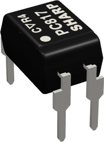
On the ESP32 DevKit V1 the page wires the PC817 as a loopback: GPIO13 lights its LED through 1 kOhm, and GPIO14 reads its collector with the ESP32's internal pull-up. With a 1.2 V LED drop, 3.3 V through 1 kOhm gives the LED about 2 mA, enough for the transistor to pull a weak pull-up down.
Wiring the PC817 Optocoupler to the ESP32 DevKit V1
Pin by pin.
| PC817 Optocoupler | ESP32 DevKit V1 | Note |
|---|---|---|
| A | GPIO13 (D13) | through a 1 kΩ resistor |
| K | GND | |
| C | GPIO14 (D14) | |
| E | GND |
What to know on the ESP32 DevKit V1
- The ESP32's internal pull-up is about 45 kOhm, so the collector only needs to sink tens of microamps to read LOW; even the PC817's lowest transfer ratio, 50 % at 5 mA, leaves plenty of margin at about 2 mA of LED current.Espressif ESP32 Series Datasheet v5.3, p. 52; Sharp PC817XNNSZ0F sheet OP14004EN, pp. 3, 5
- Do not move the collector to GPIO34 to GPIO39 with INPUT_PULLUP: those pins have no internal pull resistors. Use another pin or add a 10 kOhm pull-up to 3.3 V.Espressif ESP32 Series Datasheet v5.3, p. 61
- In the page's loopback both K and E go to the DevKit's GND, so nothing is isolated. To isolate a real circuit, drive the LED from that circuit and keep its ground off the ESP32's; only the collector and emitter touch the ESP32.Sharp PC817XNNSZ0F sheet OP14004EN, p. 3
PC817 Optocoupler code for the ESP32 DevKit V1
Compiled for esp32:esp32:esp32 on 2026-10-29.
// PC817 Optocoupler on ESP32 DevKit V1: wiring and a free simulation at https://www.tinkered.ai/components/pc817/esp32
const int LED_PIN = 13;   // PC817 pin 1 (anode) through 1 kOhm
const int OUT_PIN = 14;   // PC817 pin 4 (collector), pin 3 (emitter) to GND

void setup() {
  Serial.begin(9600);
  pinMode(LED_PIN, OUTPUT);
  pinMode(OUT_PIN, INPUT_PULLUP);   // the transistor only pulls down
}

void loop() {
  digitalWrite(LED_PIN, HIGH);
  delay(500);
  Serial.print("LED on:  output ");
  Serial.println(digitalRead(OUT_PIN) == LOW ? "LOW (conducting)" : "HIGH");
  digitalWrite(LED_PIN, LOW);
  delay(500);
  Serial.print("LED off: output ");
  Serial.println(digitalRead(OUT_PIN) == LOW ? "LOW" : "HIGH (off)");
}
PC817 Optocoupler on the ESP32 DevKit V1: questions
Can an ESP32 GPIO drive a PC817 LED directly?
Yes, through a resistor. The LED drops about 1.2 V (Sharp sheet, p. 3), so 1 kOhm from a 3.3 V pin gives about 2 mA, well under the 50 mA maximum and within an ESP32 pin's drive.
Why does the PC817 output read LOW all the time on my ESP32?
Check that the collector, pin 4, goes to the GPIO and the emitter, pin 3, to GND, and that the pin has a pull-up: INPUT_PULLUP on most pins, an external resistor on GPIO34 to GPIO39 (ESP32 datasheet, p. 61).
Keep going
This guide as plain Markdown. /components/pc817/esp32.md