PC817 Optocoupler with an Arduino Uno
The PC817 is a 4-pin optocoupler that passes a signal through light across 5 kV of isolation, so a 12 V or 24 V circuit can talk to a microcontroller safely.
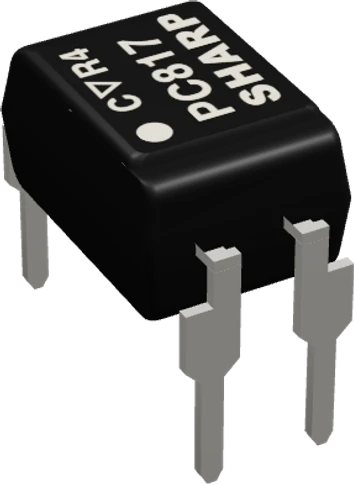
On an Arduino Uno the PC817's LED is driven from D7 through 1 kΩ and its phototransistor pulls D2 low against the Uno's internal pull-up. Both sides share the Uno's GND in this test wiring, which shows the logic; real isolation comes when the LED side belongs to another circuit.
Wiring the PC817 Optocoupler to the Arduino Uno
Pin by pin.
| PC817 Optocoupler | Arduino Uno | Note |
|---|---|---|
| A | D7 | through a 1 kΩ resistor |
| K | GND | |
| C | D2 | |
| E | GND |
What to know on the Arduino Uno
- From D7's 5 V, a 1.2 V LED and 1 kΩ give (5 - 1.2) / 1000, about 3.8 mA: well under the LED's 50 mA rating and the Uno pin's 20 mA, and close to the 5 mA at which Sharp states the current transfer ratio.Sharp PC817XNNSZ0F sheet OP14004EN, p. 3; Arduino UNO R3 tech specs
- Even the lowest transfer ratio, 50 % at 5 mA, lets the transistor sink a couple of milliamps, far more than the Uno's internal pull-up supplies, so D2 reads a clean LOW with INPUT_PULLUP and no external resistor.Sharp PC817XNNSZ0F sheet OP14004EN, pp. 3, 5
- Sharp's 4 µs rise and 3 µs fall are measured with a 100 Ω load; with the Uno's much weaker internal pull-up the output rises far more slowly, fine for signals but not for fast pulses. Add a 1 kΩ to 10 kΩ pull-up to 5V for faster edges.Sharp PC817XNNSZ0F sheet OP14004EN, p. 3
- To isolate for real, keep only the emitter on the Uno's GND and the collector on D2; the LED and its cathode then belong to the other circuit's supply and ground, never joined to the Uno's.Sharp PC817XNNSZ0F sheet OP14004EN, pp. 1, 2
PC817 Optocoupler code for the Arduino Uno
Compiled for arduino:avr:uno on 2026-10-29.
// PC817 Optocoupler on Arduino Uno: wiring and a free simulation at https://www.tinkered.ai/components/pc817/arduino-uno
const int LED_PIN = 7;   // PC817 pin 1 (anode) through 1 kOhm
const int OUT_PIN = 2;   // PC817 pin 4 (collector), pin 3 (emitter) to GND

void setup() {
  Serial.begin(9600);
  pinMode(LED_PIN, OUTPUT);
  pinMode(OUT_PIN, INPUT_PULLUP);   // the transistor only pulls down
}

void loop() {
  digitalWrite(LED_PIN, HIGH);
  delay(500);
  Serial.print("LED on:  output ");
  Serial.println(digitalRead(OUT_PIN) == LOW ? "LOW (conducting)" : "HIGH");
  digitalWrite(LED_PIN, LOW);
  delay(500);
  Serial.print("LED off: output ");
  Serial.println(digitalRead(OUT_PIN) == LOW ? "LOW" : "HIGH (off)");
}
PC817 Optocoupler on the Arduino Uno: questions
What resistor does a PC817 need on an Arduino Uno?
With the LED driven from a Uno pin at 5 V, 1 kΩ gives about 3.8 mA (forward voltage 1.2 V typical, Sharp sheet p. 3). For a 12 V or 24 V signal on the input side, size the resistor for a few milliamps from that voltage instead.
Why does the PC817 output read LOW when the LED is on?
The phototransistor pulls D2 to GND when lit; the Uno's INPUT_PULLUP holds it HIGH otherwise. Treat LOW as 'signal present'.
Is the Uno isolated in this PC817 wiring?
Not in the example, where the LED's cathode and the emitter both use the Uno's GND. For isolation, connect only the transistor side to the Uno and keep the LED side's ground separate.
Keep going
This guide as plain Markdown. /components/pc817/arduino-uno.md