PWM LED strip dimmer
Low-side switching a single-color 12V LED strip with an Arduino PWM pin. The IRLZ44N is the community-standard FET for this because 5V drive fully enhances it and its low RDS(on) keeps it cool at strip currents.
Logic-level N-channel HEXFET power MOSFET that switches up to 47A at 55V and turns fully on from a 5V gate.
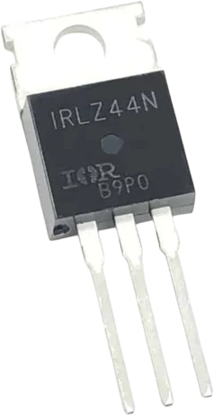
The IRLZ44N is a logic-level N-channel power MOSFET in a TO-220AB package. Its defining feature is that on-resistance is specified with only a 5V gate drive (0.025 ohm at VGS=5V, ID=25A), so a 5V microcontroller or logic output can switch it fully on without a dedicated gate-driver chip. It handles 55V drain-to-source and 47A of continuous drain current at 25C (33A at 100C), which makes it a common choice for switching high-current loads from a small logic signal.
Electrically it behaves as a voltage-controlled low-side switch. The gate threshold (VGS(th)) sits between 1.0V and 2.0V, but full enhancement and the lowest on-resistance are only reached near 4-5V, which is exactly why it is marketed as logic-level. The very low RDS(on) means it dissipates little heat at moderate currents, and an integral body diode conducts from source to drain. The gate looks like a small capacitor (total gate charge about 48nC, input capacitance around 1700pF), so it draws current only during switching transitions.
In practice the IRLZ44N is used to turn high-power loads such as DC motors, pumps, fans, heaters, solenoids, and LED strips on and off (or PWM them) from an Arduino or similar board. Because it is an N-channel device driven from ground, it belongs on the low side of the load. Note that 3.3V logic does not fully enhance it, so it is best paired with 5V drive when switching significant current.
| Pin | Function | Type |
|---|---|---|
S Source | Passive | Passive |
G Gate | Analog | Digital input |
D Drain | Passive | Passive |
Verified from the Tinkered component library.
The threshold voltage is only 1-2V, so the part starts conducting at low gate voltage, but the rated 0.025 ohm on-resistance needs about 5V. At 3.3V the channel is only partly open, so it runs hot at high current. Use 5V drive, a gate driver, or a true 3.3V logic-level FET.
A MOSFET gate is high impedance. If the only thing on the gate is the microcontroller pin, it floats during reset or power-up and the load can flicker or switch on by itself. Always add a pulldown resistor (around 10k) from gate to ground.
An N-channel MOSFET needs its gate above its source to turn on. On the high side the source sits at the load voltage, so a 5V logic pin cannot switch it. Put it on the low side (source to ground) or use a dedicated high-side driver.
The TO-220 tab and heatsink pad are internally connected to the Drain, not the Source. Mounting it directly to a grounded chassis or shared heatsink shorts the drain. Use an insulating thermal pad and bushing when the heatsink is grounded or shared.
Motors, relays, pumps, and solenoids generate a large voltage spike when the FET turns off. Without a freewheeling diode across the load, that spike stresses the MOSFET and can couple back into the microcontroller.
Low-side switching a single-color 12V LED strip with an Arduino PWM pin. The IRLZ44N is the community-standard FET for this because 5V drive fully enhances it and its low RDS(on) keeps it cool at strip currents.
Turning a 12V DC motor, water pump, or fan on and off (or PWM speed control) from a microcontroller, with a flyback diode across the load to absorb turn-off spikes.

resistor-220Custom resistance values supported

resistor-1kCustom resistance values supported

resistor-10kCustom resistance values supported
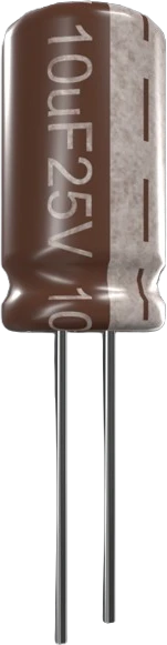
capacitor-ceramicCustom capacitance values supported
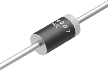
diode-1n4007General-purpose rectifier
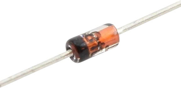
diode-1n4148Fast switching diode
Drop the IRLZ44N MOSFET into a circuit, write firmware, and simulate it in your browser, then deploy to real hardware. All in one editable Tinkered project.