Logic Level Converter (4-ch) with a Raspberry Pi Pico
A 4-channel bi-directional logic level converter that lets 3.3 V and 5 V parts share I2C, UART and digital lines safely.
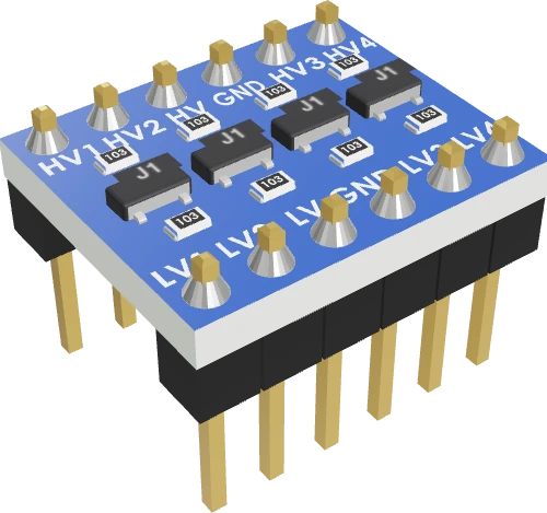
This is the part that lets a 3.3 V Raspberry Pi Pico talk to 5 V devices: LV on the Pico's 3V3, HV on VBUS, and each signal through its own channel. On this page channels 1 and 2 carry I2C0 (GP4 SDA, GP5 SCL) to a 5 V I2C LCD, and channels 3 and 4 carry an ultrasonic sensor's TRIG (GP14) and ECHO (GP15).
Wiring the Logic Level Converter (4-ch) to the Raspberry Pi Pico
Pin by pin.
| Logic Level Converter (4-ch) | Raspberry Pi Pico | Note |
|---|---|---|
| LV | 3V3 | |
| HV | VBUS | |
| GND | GND | |
| LV1 | GP4 | |
| LV2 | GP5 | |
| LV3 | GP14 | |
| LV4 | GP15 | |
| HV1 | LCD 1602 I2C SDA | |
| HV2 | LCD 1602 I2C SCL | |
| HV3 | HC-SR04 TRIG | |
| HV4 | HC-SR04 ECHO | |
| LCD and HC-SR04 VCC | the 5 V rail that feeds HV | their GND to GND |
- HV is on VBUS, which gives about 5 V only while the board is powered from USB.
What to know on the Raspberry Pi Pico
- Each channel has a 10 kOhm pull-up to LV and another to HV, so the Pico's side idles at 3.3 V and the 5 V device's side at 5 V; add no other pull-ups on the I2C lines.SparkFun Logic_Level_Bidirectional schematic (BOB-12009)
- Both supplies are required and HV must be the higher. HV on VBUS is 5 V only while USB powers the Pico; on battery through VSYS, VBUS is 0 V and no channel shifts.SparkFun hookup guide; NXP AN10441, p. 4; Raspberry Pi Pico datasheet, release 21, p. 8
- It suits I2C at 100 kbit/s and 400 kbit/s, which covers the Pico's Wire bus to an LCD backpack, but not high-speed mode.NXP AN10441, p. 3
- Do not route WS2812 data or an analog signal through it: its slow rising edge garbles 0.4 µs NeoPixel bits, and it only passes HIGH and LOW. For a 5 V analog output into GP26 to GP28, use a resistor divider.WS2812B datasheet, bit timing; Raspberry Pi Pico datasheet, release 21, p. 19
Logic Level Converter (4-ch) code for the Raspberry Pi Pico
Compiled for rp2040:rp2040:rpipico on 2026-10-30.
// Logic Level Converter (4-ch) on Raspberry Pi Pico: wiring and a free simulation at https://www.tinkered.ai/components/logic-level-converter/raspberry-pi-pico
#include <Arduino.h>
#include <Wire.h>
#include <LiquidCrystal_I2C.h>

LiquidCrystal_I2C lcd(0x27, 16, 2);
const int TRIG = 14, ECHO = 15;   // through channels 3 and 4

void setup() {
  Serial.begin(115200);
  Wire.begin();                   // GP4 SDA, GP5 SCL, through channels 1 and 2
  lcd.init();                     // the library's entry point: starts Wire and the 16x2 display
  lcd.backlight();
  lcd.print("3V3 <-> 5V ok");
  pinMode(TRIG, OUTPUT);
  pinMode(ECHO, INPUT);
}

void loop() {
  digitalWrite(TRIG, LOW);
  delayMicroseconds(2);
  digitalWrite(TRIG, HIGH);
  delayMicroseconds(10);
  digitalWrite(TRIG, LOW);
  float cm = pulseIn(ECHO, HIGH, 30000) / 58.0;
  lcd.setCursor(0, 1);
  lcd.print("Dist ");
  lcd.print(cm, 1);
  lcd.print(" cm   ");
  Serial.println(cm, 1);
  delay(200);
}
Logic Level Converter (4-ch) on the Raspberry Pi Pico: questions
How do I connect a 5 V I2C LCD to a Raspberry Pi Pico?
Power the LCD from VBUS, LV to 3V3, HV to VBUS, GND common; GP4 to LV1 and GP5 to LV2, the LCD's SDA to HV1 and SCL to HV2. The sketch then starts the bus with Wire.begin() and the display with lcd.init(), as on any board.
Can I use this converter for an HC-SR04 on a Pico?
Yes, one channel per signal: TRIG from GP14 through LV3/HV3 and ECHO back through HV4/LV4 to GP15, as the page's code does.
Why does nothing pass through the converter?
Check that LV is on 3V3, HV on VBUS, and GND joined, and that the Pico is on USB: VBUS is 0 V without it (Pico datasheet, p. 8). LV and HV swapped also stops every channel (NXP AN10441, p. 4).
This guide as plain Markdown. /components/logic-level-converter/raspberry-pi-pico.md