STM32 Blue Pill (F103C8)
A cheap 53 x 23 mm STM32F103C8T6 board: 72 MHz Cortex-M3, 64 KB flash, 20 KB RAM, USB and 3.3 V I/O.
- MicrocontrollerSTM32F103C8T6, Arm Cortex-M3, up to 72 MHz
- Memory64 KB flash, 20 KB SRAM
- Chip supply voltage2.0 V to 3.6 V
- GPIO and ADC (LQFP48)37 GPIO; 2 x 12-bit ADC, 10 channels
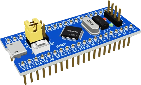
The Blue Pill is a 53 x 23 mm board around ST's STM32F103C8T6, a 72 MHz Arm Cortex-M3 with 64 KB of flash and 20 KB of SRAM running from 2.0 V to 3.6 V (ST STM32F103x8 datasheet, pp. 1, 10; stm32-base.org). Power it from micro-USB, a 5V pin or a 3.3V pin, one at a time, and wire parts to its 3.3 V pins; most are 5 V tolerant in digital mode, but PA0 to PA7, PB0, PB1, PB5 and PC13 to PC15 are not (datasheet pin table, pp. 28 to 32). Program it with an ST-LINK on the SWD header, or over USART1 (PA9, PA10) with the BOOT0 jumper set to 1 (datasheet p. 15).
The Blue Pill is the best-known STM32 board: a small blue PCB, sold by many makers, built around ST's STM32F103C8T6. It has an 8 MHz crystal for the main clock, a 32.768 kHz crystal for the real-time clock, a micro-USB socket wired to the chip's USB pins (PA11, PA12), a 3.3 V regulator, a RESET button, BOOT0 and BOOT1 jumpers, a power LED, a user LED on PC13 and a 4-pin SWD header. Two 20-pin headers 0.6 in apart let it straddle a breadboard (stm32-base.org).
The STM32F103C8 is a medium-density Cortex-M3 at up to 72 MHz with 64 KB of flash and 20 KB of SRAM in a 48-pin LQFP package, with 37 GPIO and 10 ADC channels in that package (ST datasheet, pp. 1, 10). It brings two 12-bit 1 µs ADCs, three general-purpose timers plus an advanced-control timer, two I2C, three USARTs, two SPI, a CAN 2.0B controller and a full-speed USB 2.0 device (pp. 1, 10). There is no DAC.
It runs Arduino code through the STM32duino core, as well as ST's STM32Cube HAL, libopencm3 and others. Out of the box it has no USB bootloader: the chip's built-in bootloader reprograms flash over USART1 only (datasheet p. 15), so most people flash it with a cheap ST-LINK V2 on the SWD header. Many boards on the market carry clone chips (CS32F103, APM32F103 and others) rather than ST's, which mostly behave the same but can be refused by ST's tools.
STM32 Blue Pill (F103C8) pinout
| Pin | Function | Type |
|---|---|---|
| GND | GND (G) | power in |
| GND_2 | GND_2 (G) | power in |
| 3V3 | 3V3 (3.3)3.3 V | power out |
| NRST | Digital3.3 V | input |
| PB11 | Digital, I2C2 SDA, PWM, UART USART3 RX3.3 V, 5 V tolerant | bidirectional |
| PB10 | Digital, I2C2 SCL, PWM, UART USART3 TX3.3 V, 5 V tolerant | bidirectional |
| PB1 | Digital, ADC12_IN9, PWM3.3 V | bidirectional |
| PB0 | Digital, ADC12_IN8, PWM3.3 V | bidirectional |
| PA7 | Digital, ADC12_IN7, SPI1 MOSI, PWM3.3 V | bidirectional |
| PA6 | Digital, ADC12_IN6, SPI1 MISO, PWM3.3 V | bidirectional |
| PA5 | Digital, ADC12_IN5, SPI1 SCK3.3 V | bidirectional |
| PA4 | Digital, ADC12_IN4, SPI1 NSS3.3 V | bidirectional |
| PA3 | Digital, ADC12_IN3, PWM, UART USART2 RX3.3 V | bidirectional |
| PA2 | Digital, ADC12_IN2, PWM, UART USART2 TX3.3 V | bidirectional |
| PA1 | Digital, ADC12_IN1, PWM, UART USART2 RTS3.3 V | bidirectional |
| PA0 | Digital, ADC12_IN0, PWM, UART USART2 CTS3.3 V | bidirectional |
| PC15 | Digital3.3 V | bidirectional |
| PC14 | Digital3.3 V | bidirectional |
| PC13 | Digital3.3 V | bidirectional |
| VBAT | VBAT (VB): the backup domain (RTC, BKP), a coin cell keeps it | power in |
| PB12 | Digital, SPI2 NSS3.3 V, 5 V tolerant | bidirectional |
| PB13 | Digital, SPI2 SCK, PWM, UART USART3 CTS3.3 V, 5 V tolerant | bidirectional |
| PB14 | Digital, SPI2 MISO, PWM, UART USART3 RTS3.3 V, 5 V tolerant | bidirectional |
| PB15 | Digital, SPI2 MOSI, PWM3.3 V, 5 V tolerant | bidirectional |
| PA8 | Digital, PWM3.3 V, 5 V tolerant | bidirectional |
| PA9 | Digital, PWM, UART USART1 TX3.3 V, 5 V tolerant | bidirectional |
| PA10 | Digital, PWM, UART USART1 RX3.3 V, 5 V tolerant | bidirectional |
| PA11 | Digital, CAN CAN RX, PWM, UART USART1 CTS, USB USB D-3.3 V, 5 V tolerant | bidirectional |
| PA12 | Digital, CAN CAN TX, UART USART1 RTS, USB USB D+3.3 V, 5 V tolerant | bidirectional |
| PA15 | Digital, SPI1 NSS, PWM3.3 V, 5 V tolerant | bidirectional |
| PB3 | Digital, SPI1 SCK, PWM3.3 V, 5 V tolerant | bidirectional |
| PB4 | Digital, SPI1 MISO, PWM3.3 V, 5 V tolerant | bidirectional |
| PB5 | Digital, SPI1 MOSI, PWM3.3 V | bidirectional |
| PB6 | Digital, I2C1 SCL, PWM, UART USART1 TX3.3 V, 5 V tolerant | bidirectional |
| PB7 | Digital, I2C1 SDA, PWM, UART USART1 RX3.3 V, 5 V tolerant | bidirectional |
| PB8 | Digital, CAN CAN RX, I2C1 SCL, PWM3.3 V, 5 V tolerant | bidirectional |
| PB9 | Digital, CAN CAN TX, I2C1 SDA, PWM3.3 V, 5 V tolerant | bidirectional |
| 5V | 5V (5V) | power in |
| GND_3 | GND_3 (G) | power in |
| 3V3_2 | 3V3_2 (3.3) | power out |
Specifications
- Microcontroller
- STM32F103C8T6, Arm Cortex-M3, up to 72 MHzST STM32F103x8 datasheet (Doc ID 13587 Rev 14), p. 1
- Memory
- 64 KB flash, 20 KB SRAMST STM32F103x8 datasheet, Table 2, p. 10
- Chip supply voltage
- 2.0 V to 3.6 VST STM32F103x8 datasheet, p. 1
- GPIO and ADC (LQFP48)
- 37 GPIO; 2 x 12-bit ADC, 10 channelsST STM32F103x8 datasheet, Table 2, p. 10
- I/O current
- ±8 mA normal, ±20 mA with relaxed levels; 25 mA absolute max per pin, 150 mA totalST STM32F103x8 datasheet, pp. 38, 65
- PC13 to PC15
- Sink 3 mA at most, 2 MHz max, never source currentST STM32F103x8 datasheet, pin table note 5, p. 32
- Board regulator
- TX6211B, 3.6 V to 5.5 V in, 3.3 V at 300 mA outstm32-base.org, Blue Pill
- Board clocks
- 8 MHz HSE crystal, 32.768 kHz LSE crystalstm32-base.org, Blue Pill
- User LED
- PC13, wired as a sink (lit LOW)stm32-base.org, Blue Pill
- Board size
- 23 x 53 mmstm32-base.org, Blue Pill
- Logic level
- 3.3 V
- Clock speed
- 72 MHz
- Flash
- 64 KB
- RAM
- 20 KB
- GPIO pins
- 32
- ADC channels
- 10
- ADC resolution
- 12 bits
- PWM channels
- 15
- Dimensions
- 53 × 22.6 × 19.6 mm
- Weight
- 4 g
From the generic (STMicroelectronics STM32F103C8T6)'s datasheet, published by generic (STMicroelectronics STM32F103C8T6).
Common mistakes
Expecting it to upload over USB like an Arduino
The stock chip has no USB bootloader; its ROM bootloader works over USART1 (PA9, PA10) only (ST datasheet p. 15). Use an ST-LINK on the SWD header, or a USB-serial adapter with BOOT0 set to 1, or flash a USB bootloader first.
Driving 5 V into a non-FT pin
PA0 to PA7, PB0, PB1, PB5 and PC13 to PC15 are not 5 V tolerant (datasheet pp. 28 to 32). These are also the ADC pins, so a 5 V analog sensor needs a divider.
Using PC13 as a current source
PC13 to PC15 can sink only 3 mA and must not source current (datasheet p. 32). The on-board LED on PC13 is lit by driving the pin LOW.
USB not recognised
Many Blue Pills fit a 10 kΩ or 4.7 kΩ pull-up on D+ instead of the 1.5 kΩ that USB needs (stm32-base.org; datasheet p. 74). Replacing it with 1.5 kΩ fixes enumeration on most PCs.
Leaving BOOT0 at 1
With BOOT0 at 1 the chip starts its serial bootloader instead of your program after every reset. Move the jumper back to 0 once flashing is done.
STM32 Blue Pill (F103C8) questions
Is the STM32 Blue Pill 5 V tolerant?
Partly. Pins marked FT tolerate 5 V as digital inputs, but PA0 to PA7, PB0, PB1, PB5 and PC13 to PC15 do not, and no pin does in analog mode (ST STM32F103x8 datasheet, pin table pp. 28 to 32). The chip itself runs from 2.0 V to 3.6 V (p. 1).
Why won't my Blue Pill upload?
With an ST-LINK, check the four SWD wires (3.3, SWDIO, SWCLK, GND) and try holding RESET while the upload starts. Over serial, set BOOT0 to 1, press RESET and use PA9 (TX) and PA10 (RX) (ST datasheet p. 15). If ST's software refuses the chip ID, the board may carry a clone chip, which some tools need configured separately.
Blue Pill vs Black Pill: which should I buy?
WeAct's STM32F411 Black Pill has a 100 MHz Cortex-M4 with FPU, 512 KB of flash, 128 KB of SRAM and USB-C, and its ROM bootloader flashes over USB DFU (ST STM32F411xC/xE datasheet, pp. 1, 12, 20). The Blue Pill's F103 has 72 MHz, 64 KB and 20 KB (ST STM32F103x8 datasheet, p. 10) and needs an ST-LINK or serial adapter. Choose the F411 Black Pill for new projects and the Blue Pill for existing F103 code.
Does the Blue Pill have 64 KB or 128 KB of flash?
ST specifies the STM32F103C8 with 64 KB of flash; 128 KB is the STM32F103CB (ST datasheet, Table 2, p. 10). Many C8 chips accept writes past 64 KB, which is why PlatformIO offers a bluepill_f103c8_128k option, but only 64 KB is guaranteed and clone chips may not have more.
Which pin is the Blue Pill's built-in LED?
PC13, wired as a sink so it lights when the pin is LOW (stm32-base.org). PC13 can sink only 3 mA (ST datasheet p. 32), which is enough for the on-board LED but not for driving other loads.
How much current can the Blue Pill's 3.3V pin supply?
The reference board's TX6211B regulator is rated 300 mA at 3.3 V (stm32-base.org), shared with the MCU and its LEDs. Sensors and small modules are fine; motors, servos and Wi-Fi modules need their own supply.
Build something with the STM32 Blue Pill (F103C8)
- Build this
USB HID device
Use the F103's USB to build a custom keyboard, game controller or macro pad.
- Build this
CAN bus node
Add a CAN transceiver and read or send messages on a car or robot CAN network.
- Build this
Motor and robot controller
Use the advanced-control timer's complementary PWM to drive motors and read encoders.
- Build this
Data logger
Sample analog sensors with the 12-bit ADC and log them to an SD card over SPI.
This page as plain Markdown, for ChatGPT, Claude or your own agent. /components/stm32-bluepill-f103c8.md