STM32 Blue Pill vs Black Pill F411
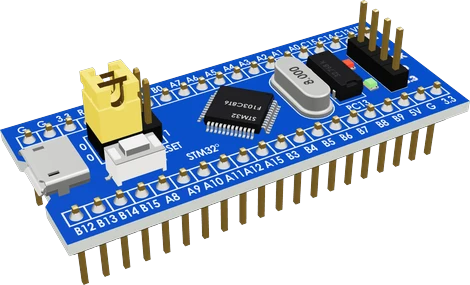
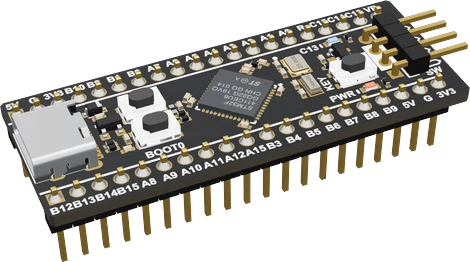
The F411 Black Pill is the stronger board: a 100 MHz Cortex-M4 with FPU, 512 KB of flash and 128 KB of SRAM, USB-C and a ROM bootloader that flashes over USB DFU (ST STM32F411xC/xE datasheet, pp. 1, 12, 20), against the Blue Pill's 72 MHz Cortex-M3 with 64 KB of flash and 20 KB of SRAM, which needs an ST-LINK or a serial adapter (ST STM32F103x8 datasheet, pp. 1, 10, 15). The Blue Pill keeps two things the F411 lacks: a CAN controller and a second ADC. Pick the Black Pill for new projects and the Blue Pill for CAN or existing F103 code.
Side by side
| STM32 Blue Pill | Black Pill F411 | |
|---|---|---|
| MicrocontrollerST STM32F103x8 datasheet (Doc ID 13587 Rev 14), p. 1; ST STM32F411xC/xE datasheet (DocID026289 Rev 7), p. 1 | STM32F103C8T6, Arm Cortex-M3, up to 72 MHz | STM32F411CEU6, Arm Cortex-M4 with FPU, up to 100 MHz |
| MemoryST STM32F103x8 datasheet, Table 2, p. 10; ST STM32F411xC/xE datasheet, Table 2, p. 12 | 64 KB flash, 20 KB SRAM | 512 KB flash, 128 KB SRAM |
| ADCST STM32F103x8 datasheet, Table 2, p. 10; ST STM32F411xC/xE datasheet, Table 2, p. 12 | 2 × 12-bit ADC, 10 channels | 1 × 12-bit ADC, 10 channels |
| CANST STM32F103x8 datasheet, Table 2, p. 10; ST STM32F411xC/xE datasheet, Table 2, p. 12 | Yes, 1 CAN controller | None |
| Upload without a programmerST STM32F103x8 datasheet, p. 15; ST STM32F411xC/xE datasheet, p. 20 | Serial bootloader on USART1 (PA9, PA10) with BOOT0 = 1 | USB DFU bootloader on PA11/PA12 over USB-C |
| 5 V tolerant pinsST STM32F103x8 datasheet, pp. 28 to 32; ST STM32F411xC/xE datasheet, pp. 39 to 46 | Most digital pins; not PA0 to PA7, PB0, PB1, PB5, PC13 to PC15 | Every header GPIO except PA0 and PB5 |
| Chip supplyST STM32F103x8 datasheet, p. 1; ST STM32F411xC/xE datasheet, Table 2, p. 12 | 2.0 V to 3.6 V | 1.7 V to 3.6 V |
| Board crystalsstm32-base.org, Blue Pill; WeAct MiniSTM32F4x1 README | 8 MHz HSE, 32.768 kHz LSE | 25 MHz HSE, 32.768 kHz LSE |
| USB connector and LEDstm32-base.org, Blue Pill; WeAct MiniSTM32F4x1 V3.1 schematic | Micro-USB; LED on PC13, lit LOW | USB-C; LED on PC13, lit LOW, KEY button on PA0 |
Which one to pick
- CAN bus projects, using the F103's built-in CAN controller with an external transceiver (ST STM32F103x8 datasheet, p. 10).
- Two ADCs sampling at the same time, for example voltage and current together (p. 10).
- Existing STM32F103 code, libraries and tutorials, which target this exact chip.
- New projects that need speed or memory: 100 MHz with a floating point unit, 512 KB of flash and 128 KB of SRAM (ST STM32F411xC/xE datasheet, pp. 1, 12).
- Flashing over a plain USB-C cable with DFU, with no ST-LINK or serial adapter (p. 20).
- I2S audio and boards mixing 5 V parts: five SPI/I2S interfaces, and every header pin but PA0 and PB5 is 5 V tolerant as a digital input (pp. 12, 39 to 46).
Swapping one for the other
What changes in the wiring and the code.
- Both run 3.3 V logic. Check 5 V inputs against each chip's list: on the Blue Pill PA0 to PA7, PB0, PB1, PB5 and PC13 to PC15 are not 5 V tolerant (F103 datasheet, pp. 28 to 32); on the Black Pill only PA0 and PB5 are not (F411 datasheet, pp. 39 to 46).
- In STM32duino select BLACKPILL_F411CE instead of the Blue Pill F103C8. Code written with HAL calls for the F1 family needs the F4 equivalents; Arduino-level code usually compiles unchanged.
- Upload changes: hold BOOT0, tap NRST, release BOOT0 and upload with the DFU method over USB-C (WeAct README), instead of an ST-LINK or USART1 with BOOT0 at 1.
- PC13 is the LED on both, lit LOW, and sinks 3 mA at most (F103 datasheet, p. 32; F411 datasheet, p. 46). On the Black Pill, PA0 is the KEY button to ground, so enable INPUT_PULLUP and do not reuse PA0 for a 5 V signal.
- CAN code has no target on the F411: keep a Blue Pill or add an SPI CAN controller. STM32duino runs the F411 at 96 MHz so USB gets an exact 48 MHz (BLACKPILL_F411CE variant).
STM32 Blue Pill or Black Pill F411: questions
Is the Black Pill better than the Blue Pill?
For most projects, yes: the STM32F411 Black Pill has a 100 MHz Cortex-M4 with FPU, 512 KB of flash, 128 KB of SRAM and USB DFU upload (ST STM32F411xC/xE datasheet, pp. 1, 12, 20). The Blue Pill's F103 has 72 MHz, 64 KB and 20 KB (ST STM32F103x8 datasheet, p. 10), but it has CAN and a second ADC.
Can I upload to both over USB?
Only the F411 Black Pill out of the box: its ROM bootloader supports USB DFU (F411 datasheet, p. 20). The F103's ROM bootloader works over USART1 on PA9 and PA10 only (F103 datasheet, p. 15), so the Blue Pill needs an ST-LINK, a USB-serial adapter or a USB bootloader flashed first.
Does the Black Pill have CAN bus?
The STM32F411 has no CAN controller (ST STM32F411xC/xE datasheet, Table 2, p. 12). The Blue Pill's STM32F103C8 has one (ST STM32F103x8 datasheet, Table 2, p. 10), which needs an external transceiver.
Which pin is the LED on each board?
PC13 on both, lit when the pin is LOW (stm32-base.org; WeAct V3.1 schematic). The Black Pill also has a KEY button on PA0 to ground.
Is the F103 Black Pill the same as the F411 Black Pill?
No. An older STM32F103C8T6 Black Pill has a micro-USB socket and its LED on PB12; the WeAct F411 Black Pill has USB-C, the STM32F411CEU6 and its LED on PC13 (WeAct V3.1 schematic). Select the board that matches the chip marking.
The two references
Checked on 2026-10-29 against 4 sources, the makers’ datasheets first.
This comparison as plain Markdown. /compare/stm32-bluepill-f103c8-vs-stm32-blackpill-f411ce.md