STM32 Black Pill (F411CE)
WeAct's USB-C STM32F411CEU6 board: 100 MHz Cortex-M4 with FPU, 512 KB flash, 128 KB RAM and USB DFU upload.
- MicrocontrollerSTM32F411CEU6, Arm Cortex-M4 with FPU, up to 100 MHz
- Memory512 KB flash, 128 KB SRAM
- Chip supply voltage1.7 V to 3.6 V
- GPIO and ADC (UFQFPN48)36 GPIO; one 12-bit ADC, 10 channels
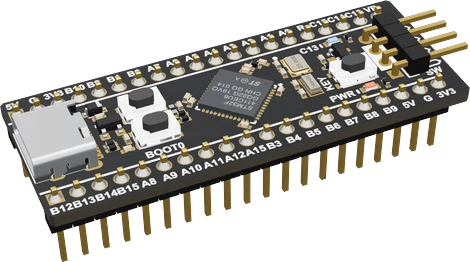
The WeAct Black Pill is a USB-C board with ST's STM32F411CEU6, an Arm Cortex-M4 with FPU at up to 100 MHz, 512 KB of flash and 128 KB of SRAM running from 1.7 V to 3.6 V (ST STM32F411xC/xE datasheet, pp. 1, 12). Power it over USB-C or 5V, wire parts at 3.3 V (every header GPIO but PA0 and PB5 is 5 V tolerant as a digital input, datasheet pp. 39 to 46), and use its blue LED on PC13 and KEY button on PA0 (WeAct V3.1 schematic). Flash it over USB: hold BOOT0, tap NRST, release BOOT0 and upload in DFU mode (WeAct README).
The Black Pill is WeAct Studio's MiniSTM32F4x1 board, now sold as V3.1 with an STM32F411CEU6 (the STM32F401 versions are discontinued). It has a USB-C socket on the chip's own USB pins (PA11, PA12), a 25 MHz crystal and a 32.768 kHz crystal, a 3.3 V LDO, three buttons (NRST, BOOT0 and a user KEY on PA0), a red power LED, a blue user LED on PC13, an SWD header and an unpopulated footprint for a W25Q SPI flash chip (WeAct README and V3.1 schematic). Its two 20-pin rows straddle a breadboard.
The STM32F411CE is a Cortex-M4 with single-precision FPU at up to 100 MHz with 512 KB of flash and 128 KB of SRAM. In the 48-pin UFQFPN package used here it has 36 GPIO, a 12-bit 2.4 MSPS ADC with 10 channels, three USARTs, three I2C, five SPI/I2S, SDIO and a full-speed USB OTG controller, with no DAC and no CAN (ST datasheet, pp. 1, 12). It runs from 1.7 V to 3.6 V. STM32duino clocks it at 96 MHz from the 25 MHz crystal so USB gets its 48 MHz.
The big step over the old F103 Blue Pill is programming: the F411's ROM bootloader supports USB DFU (datasheet p. 20), so the board flashes over its USB-C cable with no ST-LINK. It is also faster, has six times the RAM and eight times the flash of a Blue Pill, and has an FPU for maths-heavy code. Not to be confused with the older STM32F103C8T6 "Black Pill", which is a different board with a micro-USB socket and its LED on PB12.
STM32 Black Pill (F411CE) pinout
| Pin | Function | Type |
|---|---|---|
| PB12 | Digital, I2S I2S2 WS, I2S I2S3 CK, I2S I2S4 WS, SPI2 NSS, SPI3 SCK, SPI4 NSS3.3 V, 5 V tolerant | bidirectional |
| PB13 | Digital, I2S I2S2 CK, I2S I2S4 CK, SPI2 SCK, SPI4 SCK, PWM3.3 V, 5 V tolerant | bidirectional |
| PB14 | Digital, SDIO SDIO D6, SPI2 MISO, PWM3.3 V, 5 V tolerant | bidirectional |
| PB15 | Digital, I2S I2S2 SD, SDIO SDIO CK, SPI2 MOSI, PWM3.3 V, 5 V tolerant | bidirectional |
| PA8 | Digital, I2C3 SCL, SDIO SDIO D1, PWM3.3 V, 5 V tolerant | bidirectional |
| PA9 | Digital, SDIO SDIO D2, PWM, UART USART1 TX3.3 V, 5 V tolerant | bidirectional |
| PA10 | Digital, I2S I2S5 SD, SPI5 MOSI, PWM, UART USART1 RX3.3 V, 5 V tolerant | bidirectional |
| PA11 | Digital, SPI4 MISO, PWM, UART USART1 CTS, UART USART6 TX, USB USB D-3.3 V, 5 V tolerant | bidirectional |
| PA12 | Digital, SPI5 MISO, UART USART1 RTS, UART USART6 RX, USB USB D+3.3 V, 5 V tolerant | bidirectional |
| PA15 | Digital, I2S I2S1 WS, I2S I2S3 WS, SPI1 NSS, SPI3 NSS, PWM, UART USART1 TX3.3 V, 5 V tolerant | bidirectional |
| PB3 | Digital, I2C2 SDA, I2S I2S1 CK, I2S I2S3 CK, SPI1 SCK, SPI3 SCK, PWM, UART USART1 RX3.3 V, 5 V tolerant | bidirectional |
| PB4 | Digital, I2C3 SDA, SDIO SDIO D0, SPI1 MISO, SPI3 MISO, PWM3.3 V, 5 V tolerant | bidirectional |
| PB5 | Digital, I2S I2S1 SD, I2S I2S3 SD, SDIO SDIO D3, SPI1 MOSI, SPI3 MOSI, PWM3.3 V | bidirectional |
| PB6 | Digital, I2C1 SCL, PWM, UART USART1 TX3.3 V, 5 V tolerant | bidirectional |
| PB7 | Digital, I2C1 SDA, SDIO SDIO D0, PWM, UART USART1 RX3.3 V, 5 V tolerant | bidirectional |
| PB8 | Digital, I2C1 SCL, I2C3 SDA, I2S I2S5 SD, SDIO SDIO D4, SPI5 MOSI, PWM3.3 V, 5 V tolerant | bidirectional |
| PB9 | Digital, I2C1 SDA, I2C2 SDA, I2S I2S2 WS, SDIO SDIO D5, SPI2 NSS, PWM3.3 V, 5 V tolerant | bidirectional |
| 5V | 5V (V): the USB-C's VBUS through a diode, into the 3.3 V LDO | power in |
| GND | GND (G) | power in |
| 3V3 | 3V3 (V3)3.3 V | power out |
| 5V_2 | 5V_2 (5V): the USB-C's VBUS through a diode, into the 3.3 V LDO | power in |
| GND_2 | GND_2 (G) | power in |
| 3V3_2 | 3V3_2 (3V3) | power out |
| PB10 | Digital, I2C2 SCL, I2S I2S2 CK, I2S I2S3 MCK, SDIO SDIO D7, SPI2 SCK, PWM3.3 V, 5 V tolerant | bidirectional |
| PB2 | Digital, strapping3.3 V, 5 V tolerant | bidirectional |
| PB1 | Digital, ADC1_IN9, I2S I2S5 WS, SPI5 NSS, PWM3.3 V, 5 V tolerant | bidirectional |
| PB0 | Digital, ADC1_IN8, I2S I2S5 CK, SPI5 SCK, PWM3.3 V, 5 V tolerant | bidirectional |
| PA7 | Digital, ADC1_IN7, I2S I2S1 SD, SPI1 MOSI, PWM3.3 V, 5 V tolerant | bidirectional |
| PA6 | Digital, ADC1_IN6, I2S I2S2 MCK, SDIO SDIO CMD, SPI1 MISO, PWM3.3 V, 5 V tolerant | bidirectional |
| PA5 | Digital, ADC1_IN5, I2S I2S1 CK, SPI1 SCK, PWM3.3 V, 5 V tolerant | bidirectional |
| PA4 | Digital, ADC1_IN4, I2S I2S1 WS, I2S I2S3 WS, SPI1 NSS, SPI3 NSS3.3 V, 5 V tolerant | bidirectional |
| PA3 | Digital, ADC1_IN3, I2S I2S2 MCK, PWM, UART USART2 RX3.3 V, 5 V tolerant | bidirectional |
| PA2 | Digital, ADC1_IN2, PWM, UART USART2 TX3.3 V, 5 V tolerant | bidirectional |
| PA1 | Digital, ADC1_IN1, I2S I2S4 SD, SPI4 MOSI, PWM, UART USART2 RTS3.3 V, 5 V tolerant | bidirectional |
| PA0 | Digital, ADC1_IN0, PWM, UART USART2 CTS3.3 V | bidirectional |
| NRST | Digital3.3 V | input |
| PC15 | Digital3.3 V, 5 V tolerant | bidirectional |
| PC14 | Digital3.3 V, 5 V tolerant | bidirectional |
| PC13 | Digital3.3 V, 5 V tolerant | bidirectional |
| VBAT | VBAT (VB): the backup domain (RTC, backup registers), fed from 3V3 through a BAT54C when no cell is fitted | power in |
Before you wire it
- Never put 5 V on PB5: it is not 5 V tolerant (ST datasheet)
- Logic is 3.3 V. Every header GPIO except PA0 and PB5 is FT, 5 V tolerant as a digital input; PA0 and PB5 are TC and are not, and FT pins lose their 5 V tolerance in analog mode (ST datasheet pin table pp. 40, 45, note p. 46).
- Power over USB-C or the 5V pins, or with 3.3 V on 3V3, never two at once. The 5V pins feed the board's 3.3 V LDO (WeAct V3.1 schematic).
- PC13 to PC15 sit behind the backup power switch and sink only 3 mA (datasheet p. 46). The blue LED on PC13 lights when the pin is driven LOW; do not hang other loads on these pins.
- The KEY button connects PA0 to ground through 330 Ω with no pull-up on the board (WeAct V3.1 schematic), so enable the internal pull-up and read LOW when pressed.
- Keep each pin within 25 mA and all I/O together within 120 mA (datasheet p. 61). Switch motors, relays and LED strips through transistors.
- PB11 does not exist on the 48-pin package (datasheet pin table p. 42), and PA13/PA14 are on the SWD header.
Specifications
- Microcontroller
- STM32F411CEU6, Arm Cortex-M4 with FPU, up to 100 MHzST STM32F411xC/xE datasheet (DocID026289 Rev 7), p. 1
- Memory
- 512 KB flash, 128 KB SRAMST STM32F411xC/xE datasheet, Table 2, p. 12
- Chip supply voltage
- 1.7 V to 3.6 VST STM32F411xC/xE datasheet, Table 2, p. 12
- GPIO and ADC (UFQFPN48)
- 36 GPIO; one 12-bit ADC, 10 channelsST STM32F411xC/xE datasheet, Table 2, p. 12
- Interfaces
- 3 USART, 3 I2C, 5 SPI/I2S, SDIO, USB OTG full speedST STM32F411xC/xE datasheet, Table 2, p. 12
- I/O current
- 25 mA max per pin, 120 mA total for all I/OST STM32F411xC/xE datasheet, Table 12, p. 61
- Board crystals
- 25 MHz HSE, 32.768 kHz LSEWeAct MiniSTM32F4x1 README
- Buttons and LED
- NRST, BOOT0, KEY on PA0; blue LED on PC13WeAct MiniSTM32F4x1 V3.1 schematic
- USB bootloader
- USB DFU on PA11/PA12 from system memoryST STM32F411xC/xE datasheet, p. 20
- Clock under STM32duino
- 96 MHz (25 MHz / 25 x 192 / 2)STM32duino BLACKPILL_F411CE variant clock setup
- Logic level
- 3.3 V
- Clock speed
- 100 MHz max (96 MHz under STM32duino)ST STM32F411xC/E datasheet
- Flash
- 512 KB
- RAM
- 128 KB
- ADC channels
- 10
- ADC resolution
- 12 bits
- Dimensions
- 52.81 × 20.78 × 13.24 mm
- Weight
- 4 g
From the WeAct Studio (STMicroelectronics STM32F411CEU6)'s datasheet, published by WeAct Studio (STMicroelectronics STM32F411CEU6).
Common mistakes
Board not detected in DFU mode
Hold BOOT0, press and release NRST, then release BOOT0 about half a second later (WeAct README). Use a USB-C cable that carries data. WeAct notes that if the PC still does not see it, warming the chip slightly (to about 25 °C) and trying again helps.
Confusing it with the F103 Black Pill
The older STM32F103C8T6 Black Pill has a micro-USB socket, jumpers and its LED on PB12. Select the BLACKPILL_F411CE board in your core, or code and pin numbers will not match.
No Serial output on the USB-C port
Serial in STM32duino is USART1 on PA9/PA10 by default. To print over the USB-C cable, enable USB CDC in the core's USB support option so Serial uses the native USB.
Reading KEY without a pull-up
KEY ties PA0 to ground through 330 Ω and the board fits no pull-up (WeAct V3.1 schematic). Without INPUT_PULLUP the pin floats.
Sourcing current from PC13
PC13 to PC15 sink at most 3 mA (ST datasheet p. 46). The on-board LED is fine; an external LED or buzzer on these pins is not.
STM32 Black Pill (F411CE) questions
Is the STM32F411 Black Pill 5 V tolerant?
Mostly. Every header GPIO except PA0 and PB5 is an FT pin, 5 V tolerant as a digital input; PA0 and PB5 are not, and no pin is 5 V tolerant in analog mode (ST STM32F411xC/xE datasheet, pp. 39 to 46). The chip itself runs from 1.7 V to 3.6 V (p. 12).
Why won't my Black Pill upload over USB?
Put it in DFU mode first: hold BOOT0, press and release NRST, release BOOT0 after about 0.5 s (WeAct README). Then upload with the DFU method. If the PC does not list the device, try another data-capable USB-C cable; WeAct also suggests warming the chip slightly and retrying.
Blue Pill vs Black Pill: which should I buy?
The F411 Black Pill: 100 MHz Cortex-M4 with FPU, 512 KB flash, 128 KB SRAM and USB DFU upload (ST STM32F411xC/xE datasheet, pp. 1, 12, 20), against the Blue Pill's 72 MHz Cortex-M3, 64 KB and 20 KB, which needs an ST-LINK or serial adapter (ST STM32F103x8 datasheet, pp. 10, 15). The Blue Pill keeps CAN, which the F411 lacks.
Which pins are the LED and the button on the Black Pill?
The blue user LED is on PC13 and lights when the pin is LOW; the KEY button is on PA0 to ground (WeAct V3.1 schematic). In STM32duino they are LED_BUILTIN and USER_BTN.
Does the Black Pill run at 100 MHz?
The STM32F411 is rated to 100 MHz (ST datasheet p. 1), but STM32duino runs the Black Pill at 96 MHz from its 25 MHz crystal so the USB peripheral gets an exact 48 MHz (BLACKPILL_F411CE variant clock setup).
Can the Black Pill do I2S audio?
Yes. The STM32F411 has five SPI/I2S interfaces, two of them full duplex, plus an audio PLL (ST datasheet, pp. 11, 12), so it can drive an I2S amplifier or read an I2S microphone.
Build something with the STM32 Black Pill (F411CE)
- Build this
USB MIDI or HID controller
Turn knobs and buttons into a USB MIDI controller or keyboard using the F411's USB OTG.
- Build this
I2S audio player or recorder
Stream audio to an I2S amplifier or record from an I2S microphone, with the FPU for filters.
- Build this
Drone or robot flight controller
Read an IMU over SPI and run control loops at 100 MHz with hardware floating point.
- Build this
MicroPython board
Run MicroPython on the 512 KB flash and 128 KB RAM, with the optional SPI flash for files.
- Build this
Logic analyser or signal generator
Use DMA, timers and the 2.4 MSPS ADC to capture and generate signals.
This page as plain Markdown, for ChatGPT, Claude or your own agent. /components/stm32-blackpill-f411ce.md