MT3608 Boost Converter Module
A small adjustable step-up converter that boosts 2 V to 24 V up to as much as 28 V, set with a multi-turn trimmer.
- Input voltage (chip)2 V to 24 V
- Output voltage (chip)Adjustable, up to 28 V
- Switch current limit4 A (VIN 5 V, 50 % duty, guaranteed by design)
- Switching frequency1.2 MHz fixed, PFM at light load
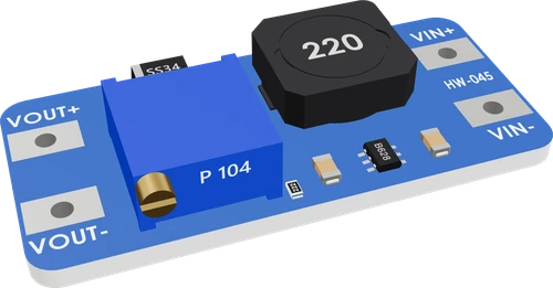
The MT3608 module is a step-up (boost) converter: its chip takes 2 V to 24 V in and regulates an output set by its trimmer up to 28 V, switching at 1.2 MHz with a 4 A internal switch limit (Aerosemi MT3608 datasheet, pp. 1, 3). Wire the source to VIN+ and VIN-, set the output with a multimeter before connecting the load, then take it from OUT+ and OUT-, which shares its ground with VIN- (ProtoSupplies MT3608 module page). Plan on about 1 A continuous out, the figure ProtoSupplies recommends for the module.
The MT3608 module is the small blue step-up converter used to run 5 V boards from a single Li-ion cell or two AA cells, or to make 9 V or 12 V from a 5 V rail. It is built around Aerosemi's MT3608, a 6-pin SOT23 current-mode boost regulator with an integrated 80 mΩ power MOSFET that switches at a fixed 1.2 MHz and moves to pulse frequency modulation at light loads (Aerosemi datasheet, pp. 1, 3).
The chip regulates its FB pin to 0.6 V, so the output is set by a resistor divider: VOUT = 0.6 V × (1 + R1 / R2) (datasheet, pp. 3, 6). On the module one leg of that divider is a multi-turn trimmer, so you dial the output in with a screwdriver while reading it on a multimeter. ProtoSupplies documents the module as 2.5 V to 24 V in and 5 V to 28 V out, with four solder pads: VIN+, VIN-, OUT+ and OUT-, the two minus pads being the same ground.
A boost converter only steps up. Its output never drops meaningfully below its input, so for a lower voltage you need a buck converter such as the LM2596. The datasheet's headline is a 2 A converter, but the 4 A figure is the internal switch's peak current, not the output current (datasheet, pp. 1, 3); because the input current is always larger than the output current in a boost, ProtoSupplies rates the module at 1.0 A continuous and 1.5 A peak, and finds it works best around 500 mA.
MT3608 Boost Converter Module pinout
| Pin | Function | Type |
|---|---|---|
| VIN | VIN+ (2-24 V in) | power in |
| GND_IN | VIN- (ground) | power in |
| VOUT | VOUT+ (adjustable out) | power out |
| GND_OUT | VOUT- (ground) | power in |
How to wire the MT3608 Boost Converter Module
Pin by pin, for the board you have.
| MT3608 Boost Converter Module | Arduino Uno | Note |
|---|---|---|
| VOUT | VIN | |
| GND_OUT | GND |
| MT3608 Boost Converter Module | ESP32 DevKit V1 | Note |
|---|---|---|
| VOUT | VIN | |
| GND_OUT | GND |
| MT3608 Boost Converter Module | Raspberry Pi Pico | Note |
|---|---|---|
| VOUT | VSYS | |
| GND_OUT | GND |
Before you wire it
- VIN+ from a supply of 2-24 V: a Li-ion cell, an AA pack, a 5 V rail. Never more than 24 V.
- VIN− to the supply's −, and the circuit's ground to VOUT− (the same copper): a board that drives parts powered by the boost shares that ground.
- Set vout to what the load takes, and above the input.
- No boost without vout= when anything with a voltage limit is on its output.
- No VIN+ above 24 V; no vout below its input (it cannot step down).
- No output on a 3.3 V part while it is set higher; no output on a board's 5V or 3V3 pin.
- Set the output before anything is connected to OUT+: power the module from its source, read OUT+ to OUT- with a multimeter and turn the trimmer. On the common module, turning counterclockwise raises the output and clockwise lowers it (ProtoSupplies), and the multi-turn trimmer can need many turns before the reading moves.
- The input always carries more current than the output. 5 V at 500 mA is 2.5 W, so a 3.7 V cell supplies at least 0.68 A before the converter's losses; size the battery, its wiring and any protection for that input current, not the load's.
- VIN- and OUT- are the same copper (ProtoSupplies). A microcontroller that drives parts powered from the boost must share that ground.
- The chip has no reverse polarity protection: its IN pin is rated -0.3 V minimum (Aerosemi datasheet, p. 2). Check polarity before connecting a battery; a reversed cell destroys it.
- The module's output ripple is about 500 mV typical in ProtoSupplies' tests; a 100 µF capacitor across OUT+ and OUT- cut their worst case from 0.9 V to 30 mV. Add one when the output feeds an ADC reference, audio or a radio.
- Feed a board through its regulated input: an ESP32 DevKit's VIN or a Pico's VSYS at 5 V, an Uno's barrel jack or VIN at a higher setting. Do not put the boost on a board's 3V3 pin.
- Turning the trimmer counterclockwise raises the output; the maximum output is 28 V.
Specifications
- Input voltage (chip)
- 2 V to 24 VAerosemi MT3608 datasheet, pp. 1, 3
- Output voltage (chip)
- Adjustable, up to 28 VAerosemi MT3608 datasheet, p. 1
- Switch current limit
- 4 A (VIN 5 V, 50 % duty, guaranteed by design)Aerosemi MT3608 datasheet, p. 3
- Switching frequency
- 1.2 MHz fixed, PFM at light loadAerosemi MT3608 datasheet, pp. 1, 3
- Feedback voltage
- 0.6 V typ (0.588 V to 0.612 V); VOUT = 0.6 V × (1 + R1/R2)Aerosemi MT3608 datasheet, pp. 3, 6
- Power MOSFET on-resistance
- 80 mΩ typ, 150 mΩ maxAerosemi MT3608 datasheet, p. 3
- Undervoltage lockout
- 1.98 V max, 100 mV hysteresisAerosemi MT3608 datasheet, p. 3
- Absolute maximum
- IN 26 V, SW 30 V, IN not below -0.3 VAerosemi MT3608 datasheet, p. 2
- Module ratings
- 2.5 V to 24 V in, 5 V to 28 V out, 1.0 A continuous, 1.5 A peakProtoSupplies MT3608 module page
- Module size
- 37 × 17 × 7 mmProtoSupplies MT3608 module page
- Maximum supply voltage
- 24 V
- Dimensions
- 37.1 × 17.2 × 7.3 mm
- Weight
- 4 g
- Maximum output voltage
- 28 Vmaker's datasheet, checked 29 Oct 2026
From the Generic (Aerosemi MT3608)'s datasheet, published by Generic (Aerosemi MT3608).
Common mistakes
Connecting the load before setting the voltage
The output comes out wherever the trimmer was left, which can be far above what a 5 V or 3.3 V part survives. Set it with a multimeter and no load first, then connect the load.
Expecting it to step down
A boost converter can only raise the voltage. Set below the input, the output just sits at the input less the diode's drop. To get 5 V from 12 V use a buck converter such as the LM2596.
Treating the 4 A figure as output current
4 A is the internal switch's current limit (Aerosemi datasheet, p. 3). The output current is far lower and falls as the step-up ratio grows; ProtoSupplies rates the module at 1.0 A continuous and notes the parts get hot under heavier loads.
Reversing the battery
There is no reverse polarity protection on the module, and the chip's IN pin is rated to -0.3 V (Aerosemi datasheet, p. 2). A cell soldered the wrong way round kills the chip at once.
Leaving it on a battery when idle
The module draws about 1 mA with no load (ProtoSupplies), enough to drain a small battery over days. Put a switch on its input if the project sits unused.
MT3608 Boost Converter Module questions
How do I set the MT3608 output voltage?
Power the input, measure OUT+ to OUT- with a multimeter and turn the trimmer: counterclockwise raises the output on the common module (ProtoSupplies). The chip holds its FB pin at 0.6 V, so the output is 0.6 V × (1 + R1/R2), the trimmer being part of that divider (Aerosemi datasheet, pp. 3, 6).
How much current can the MT3608 module supply?
Plan on about 1 A continuous: ProtoSupplies rates the module at 1.0 A continuous and 1.5 A peak and finds it works best around 500 mA. The 4 A figure in the datasheet is the switch current limit, not the output (Aerosemi datasheet, p. 3), and the higher the step-up ratio, the less output current is available.
Can I run an ESP32 or a 5 V Arduino project from one 18650 cell with an MT3608?
Yes. Set the output to 5 V before connecting, then feed an ESP32 DevKit's VIN or a Pico's VSYS, so the board's own regulator makes its 3.3 V. The cell must supply more current than the load: 5 V at 500 mA takes at least 0.68 A from a 3.7 V cell before losses.
Why does my MT3608 output the same voltage as the input?
The trimmer is set at or below the input, so the converter is not boosting and the input passes through its diode. Turn the multi-turn trimmer counterclockwise, often for many turns, while watching a multimeter (ProtoSupplies). If it still does not rise, check that the input is above the chip's 1.98 V lockout (Aerosemi datasheet, p. 3) and that the load is not past its current limit.
MT3608 vs LM2596: which one do I need?
Compare your source and your load. The MT3608 steps up, up to 28 V from a 2 V to 24 V input (Aerosemi datasheet, p. 1); the LM2596 steps down, with a 3 A output rating (TI LM2596 datasheet, p. 1). Use the MT3608 to make 5 V from a battery, the LM2596 to make 5 V from 12 V.
Can the MT3608 power a 3.3 V board directly?
It can be set to 3.3 V only when the input is below 3.3 V, since a boost never goes under its input. From a Li-ion cell, set 5 V and feed the board's 5 V input so its regulator makes 3.3 V; never put the boost on a 3V3 pin while it is set higher.
Is the MT3608 output noisy?
Somewhat: ProtoSupplies measured about 500 mV of ripple typical on the module. A 100 µF capacitor across the output cut their worst case from 0.9 V to 30 mV.
Build something with the MT3608 Boost Converter Module
18650-powered ESP32 sensor
Boost a single Li-ion cell to 5 V for an ESP32 DevKit's VIN and run a Wi-Fi sensor away from USB.
Portable USB power bank
Pair a TP4056 charger and an 18650 cell with an MT3608 set to 5 V for a home-made phone or gadget charger.
12 V LED strip from USB
Step a 5 V USB supply up to 12 V for a short LED strip segment or a small 12 V fan.
Two-AA 5 V supply
Run a small 5 V circuit from two AA cells by boosting their 3 V to 5 V.
This page as plain Markdown, for ChatGPT, Claude or your own agent. /components/mt3608-boost-module.md