MB102 Breadboard Power Module
A plug-on breadboard power supply that puts 5 V or 3.3 V on each pair of rails from a 6.5 V to 12 V adapter or USB.
- Input voltage6.5 V to 12 V DC on the jack, or 5 V on USB
- Outputs5 V and 3.3 V, chosen per side by jumper (5V, OFF, 3.3V)
- Maximum output currentUnder 700 mA
- RegulatorsAMS1117-5.0, and AMS1117-3.3 fed from the 5 V rail
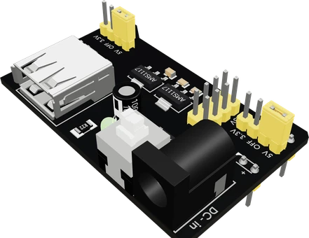
The MB102 is a breadboard power supply that plugs onto one end of a breadboard and puts 5 V, 3.3 V or nothing on each pair of rails, chosen by a jumper per side, from a 6.5 V to 12 V DC adapter or 5 V USB, for under 700 mA in all (Handson Technology MB102 datasheet, p. 1). Two AMS1117 regulators make the 5 V and the 3.3 V (schematic, Handson p. 3). Wire your parts to the rails, join the rail's ground to your microcontroller's GND, and do not feed the same rail from the board's 5V pin.
The MB102 breadboard power supply, first sold as the YwRobot module, is a small board that seats directly on the power rails at one end of a standard MB102 breadboard. It takes 6.5 V to 12 V from a DC barrel jack or 5 V from its USB-A port and delivers 5 V and 3.3 V, with a latching push switch and a green power LED (Handson Technology MB102 datasheet, pp. 1, 2).
Each side has its own three-position jumper marked 5V, OFF and 3.3V, so the top rails can be 3.3 V for a sensor while the bottom rails are 5 V for a servo (Handson, p. 2). A 2 × 4 header in the middle gives two 5 V pins, two 3.3 V pins and four grounds for jumper wires, whatever the rail jumpers say (schematic, Handson p. 3).
Inside, the jack feeds a 1N4007 reverse polarity diode, then an AMS1117-5.0 that makes the 5 V rail; an AMS1117-3.3 is fed from that 5 V rail (schematic, Handson p. 3). The USB-A port is tied straight to the 5 V rail with no protection: it powers the board when no adapter is plugged in, and outputs 5 V to a device when one is (Handson, pp. 2, 3). Both regulators are linear, so the module turns the whole voltage drop into heat, which is why its practical current falls as the adapter voltage rises.
MB102 Breadboard Power Module pinout
| Pin | Function | Type |
|---|---|---|
| TOP_VCC_1 | Top rail + (jumper-selected) | power out |
| TOP_VCC_2 | Top rail + (jumper-selected) | power out |
| TOP_GND_1 | Top rail − (GND) | power out |
| TOP_GND_2 | Top rail − (GND) | power out |
| BOT_VCC_1 | Bottom rail + (jumper-selected) | power out |
| BOT_VCC_2 | Bottom rail + (jumper-selected) | power out |
| BOT_GND_1 | Bottom rail − (GND) | power out |
| BOT_GND_2 | Bottom rail − (GND) | power out |
| 5V_1 | Header 5V | power out |
| 5V_2 | Header 5V | power out |
| 3V3_1 | Header 3.3V | power out |
| 3V3_2 | Header 3.3V | power out |
| GND_1 | Header GND | power out |
| GND_2 | Header GND | power out |
| GND_3 | Header GND | power out |
| GND_4 | Header GND | power out |
Before you wire it
- Use it to power parts from the breadboard's rails: wire their VCC to rail_top_positive / rail_bottom_positive and GND to the matching negative rail. Each side is the voltage its jumper says (5 V by default): put 3.3 V parts on a side set to 3.3 V (top=3v3) and say so to the user.
- A board that drives parts powered by the MB102 shares its GND.
- Do not also feed the same rail from the board's 5V or 3V3 pin: two supplies fight. The board stays on USB; the MB102 powers the parts.
- Servos, motors, LED strips, relays: the MB102 rather than the board's 5V pin (the board's regulator and USB cannot supply their current). Stay under 700 mA in total.
- The 2x4 header pins are 5V_1/5V_2, 3V3_1/3V3_2, GND_1..GND_4 (aliases 5V, 3V3, GND): wire from them for a supply away from the rails (pwr_1:3V3_1 → rf_1:3V3), one jumper per pin. The header gives 5 V and 3.3 V whatever the jumpers say (while switched on).
- Never onto a board's regulated pin at another voltage: a side at 5 V on an ESP32's 3V3, or a side at 3.3 V on an Uno's 5V, is flagged.
- No placing it by holes: write its position as rails.
- No parts or wires in the first 9 rows under it.
- No MB102 without a breadboard (breadboard: none).
- Join grounds: a microcontroller that drives parts powered by the MB102 must have its GND on one of the module's negative rails, or its signals have no reference.
- Do not also feed a rail the MB102 powers from the microcontroller's 5V or 3V3 pin. Two supplies on one rail fight each other. Leave the board on its USB cable and let the MB102 power the parts.
- Mind the heat from a 12 V adapter. The 5 V regulator drops about 6 V there (12 V less the input diode and the 5 V output), and AMS guarantees regulation only up to 1.2 W in SOT-223 (AMS1117 datasheet, p. 3), which is reached at about 200 mA. Use a 7 V to 9 V adapter, or USB, when you need more current.
- The 3.3 V regulator is fed from the 5 V rail (schematic, Handson p. 3), so every milliamp drawn at 3.3 V also passes through the 5 V regulator and counts toward the module's 700 mA.
- The USB-A port is joined straight to the 5 V rail with no protection (schematic, Handson p. 3). Do not connect a computer to it while an adapter is plugged into the jack: the computer's 5 V and the regulator's 5 V would be tied together.
- On the centre header, do not bridge from one row to the other: the schematic warns that this shorts 3.3 V or 5 V to ground (Handson p. 3).
Specifications
- Input voltage
- 6.5 V to 12 V DC on the jack, or 5 V on USBHandson Technology MB102 datasheet, p. 1
- Outputs
- 5 V and 3.3 V, chosen per side by jumper (5V, OFF, 3.3V)Handson Technology MB102 datasheet, pp. 1, 2
- Maximum output current
- Under 700 mAHandson Technology MB102 datasheet, p. 1
- Regulators
- AMS1117-5.0, and AMS1117-3.3 fed from the 5 V railAddicore YwRobot schematic V2, Handson datasheet p. 3
- Input protection
- 1N4007 series diode on the jack (reverse polarity)Handson Technology MB102 datasheet, pp. 1, 3
- AMS1117 dropout
- 1.1 V typ, 1.3 V max at 0.8 AAMS1117 datasheet (Advanced Monolithic Systems), p. 3
- AMS1117 output accuracy
- 3.3 V version 3.201 V to 3.399 V; 5.0 V version 4.850 V to 5.150 V over temperatureAMS1117 datasheet, p. 2
- AMS1117 power limit (SOT-223)
- Regulation guaranteed up to 1.2 W dissipationAMS1117 datasheet, p. 3, note 2
- AMS1117 current limit
- 900 mA min, 1.1 A typAMS1117 datasheet, p. 3
- Board size
- 5.3 × 3.5 cmHandson Technology MB102 datasheet, p. 1
- Supply voltage
- 5 V
- Dimensions
- 53 × 35 mmmaker's datasheet, checked 29 Oct 2026
- Weight
- 12 g
Common mistakes
No common ground with the microcontroller
Sensors and servos powered from the MB102 rails read and respond erratically if the Arduino or ESP32 has no ground in common with them. Run a wire from the board's GND to a negative rail.
Leaving a jumper in the middle
The middle position is OFF: that side's rails get nothing (Handson, p. 2). Check both jumpers when one half of the breadboard is dead.
Putting 3.3 V parts on a 5 V side
Each side carries what its jumper selects. An RC522, an nRF24L01 or another 3.3 V-only part on a side set to 5 V can be damaged; move that side's jumper to 3.3V before powering up.
Pulling servos and motors from a 12 V adapter
The linear 5 V regulator turns the drop from 12 V into heat and stops regulating past 1.2 W in SOT-223 (AMS1117 datasheet, p. 3). Use a lower adapter voltage, USB, or a switching supply for loads of a few hundred milliamps.
Mismatching the rail polarity
The module's + and - pins must land on the breadboard's + and - rails. On a breadboard whose rails are printed in the other order, the supply goes in reversed; check the markings before switching on.
MB102 Breadboard Power Module questions
What input voltage does the MB102 power supply need?
6.5 V to 12 V DC on the barrel jack, or 5 V on the USB port (Handson MB102 datasheet, p. 1). The lower limit comes from the 1N4007 input diode plus the AMS1117-5.0's dropout of 1.1 V typical, 1.3 V maximum at 0.8 A (AMS1117 datasheet, p. 3); AMS specifies the 5.0 V version with 6.5 V in (p. 2).
How much current can the MB102 supply?
Under 700 mA in all (Handson MB102 datasheet, p. 1), and the 3.3 V output's current is part of that total because its regulator is fed from the 5 V rail (Handson p. 3). From a 12 V adapter the real limit is lower, because the SOT-223 AMS1117 only guarantees regulation up to 1.2 W (AMS1117 datasheet, p. 3).
Can the MB102 power 3.3 V and 5 V parts at the same time?
Yes. Set one side's jumper to 3.3V and the other to 5V, and put each part on the matching side (Handson MB102 datasheet, p. 2). The centre header also gives both 5 V and 3.3 V at once, whatever the jumpers say (Handson p. 3).
Why is my MB102 not working or its LED off?
Press the latching switch: it cuts both the jack and the USB input (schematic, Handson p. 3). Check that the adapter is between 6.5 V and 12 V and of the right polarity, since the 1N4007 blocks a reversed one (Handson p. 1), and that each jumper is not in the middle OFF position. On a long breadboard, also check whether the rails are split halfway along.
Can I power an Arduino or ESP32 from the MB102?
Usually keep the board on its own USB and let the MB102 power servos, LEDs and sensors, with the grounds joined. Feeding a 5 V side into an Uno's 5V pin bypasses the Uno's regulator, and a 5 V side on an ESP32's 3V3 pin can destroy it; never put a side on a board's regulated pin at a different voltage.
MB102 vs LM2596 buck module: which should I use?
The MB102 is linear, so from 12 V it wastes most of the power as heat and stays under 700 mA (Handson MB102 datasheet, p. 1; AMS1117 datasheet, p. 3). The LM2596 is a switching regulator rated for 3 A (TI LM2596 datasheet, p. 1). Use the MB102 for sensors and small loads on a breadboard, a buck module for motors, LED strips and servo banks.
Can I power the MB102 from a computer's USB port?
Yes, when no adapter is plugged in: the USB port then feeds the 5 V rail directly, and the 3.3 V regulator runs from it (Handson MB102 datasheet, p. 2). The port is a USB-A socket, so it needs a cable with a USB-A plug at the module end, and the computer port's own current limit then applies.
Build something with the MB102 Breadboard Power Module
Servo test rig
Power one or two SG90 servos from the 5 V rails while an Arduino on USB drives their signals.
Mixed 3.3 V and 5 V prototype
Set one side to 3.3 V for an RFID or radio module and the other to 5 V for an LCD on the same breadboard.
Standalone breadboard circuit
Run a 555 timer, logic chips or an ATmega on a breadboard from a 9 V wall adapter, with no development board attached.
Sensor bench
Feed several sensors from the rails so the microcontroller's own regulator stays cool.
This page as plain Markdown, for ChatGPT, Claude or your own agent. /components/mb102-power-module.md