LM2596 Buck Converter Module
The classic blue step-down module: up to 40 V in, an adjustable output from a multi-turn trimmer, built on TI's 3 A LM2596.
- Input voltage (chip)4.5 V to 40 V operating; 45 V absolute maximum
- Output voltage (adjustable)1.2 V to 37 V, ±4 % over line and load
- Feedback reference1.23 V typical (1.193 V to 1.267 V at 25 °C)
- Load current (chip)3 A
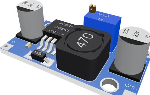
The LM2596 buck module is a step-down DC-DC converter built on TI's LM2596, a 150 kHz switching regulator rated for a 3 A load and inputs up to 40 V (TI LM2596 datasheet, p. 1). Wire the supply to IN+ and IN-, turn the trimmer while measuring OUT+ to set the voltage, then connect the load to OUT+ and OUT- with a ground shared with your microcontroller. The adjustable chip regulates from its 1.23 V feedback reference up to 37 V, always below the input (pp. 1, 6).
The LM2596 buck module is a small blue board that steps a higher DC voltage down to a lower one efficiently. It carries an LM2596S-ADJ regulator, the inductor, Schottky catch diode and capacitors its datasheet circuit needs, and a multi-turn trimmer that sets the output. Four terminals bring out IN+ and IN- at one end and OUT+ and OUT- at the other, with IN- and OUT- joined on the board.
The LM2596 is a monolithic step-down switching regulator from Texas Instruments. It switches at a fixed 150 kHz, drives a load of up to 3 A, accepts 4.5 V to 40 V on its input, and in its adjustable version sets an output from 1.2 V to 37 V through a 1.23 V feedback reference (TI LM2596 datasheet, pp. 1, 5, 6). It includes current limiting and thermal shutdown, and an ON/OFF pin that drops its standby current to about 80 µA (pp. 1, 4).
Because it switches rather than burning the difference as heat, a buck converter suits large drops: TI's test circuits reach 73 % efficiency at 3.3 V out from 12 V, 80 % at 5 V from 12 V, and 90 % at 12 V from 25 V, all at 3 A (p. 6). That makes the module a staple for powering servos, LED strips and microcontroller boards from 9 V to 24 V batteries and adapters.
LM2596 Buck Converter Module pinout
| Pin | Function | Type |
|---|---|---|
| VIN | IN+ (4.5-40 V in) | power in |
| GND_IN | IN- (ground) | power in |
| VOUT | OUT+ (adjustable out) | power out |
| GND_OUT | OUT- (ground) | power in |
How to wire the LM2596 Buck Converter Module
Pin by pin, for the board you have.
| LM2596 Buck Converter Module | Arduino Uno | Note |
|---|---|---|
| GND_OUT | GND |
| LM2596 Buck Converter Module | ESP32 DevKit V1 | Note |
|---|---|---|
| GND_OUT | GND |
| LM2596 Buck Converter Module | Raspberry Pi Pico | Note |
|---|---|---|
| GND_OUT | GND |
Before you wire it
- IN+ from a supply of 4.5-40 V: a 9 V or 12 V battery, a 4xAA pack (6 V: enough for 3.3 V out, short of 5 V), a 12 V adapter. Never from a board's output pin.
- IN− to the supply's −, and the circuit's ground to OUT− (the same copper): a board that drives parts powered by the buck shares that ground.
- Set vout to what the load takes: 5 for 5 V parts and servos; 3.3 for 3.3 V parts; 12 for 12 V strips or fans.
- Feeding a board, through its input pin: an Uno's or Nano's VIN at 7-12 V (vout=9); an ESP32 DevKit's VIN or a Pico's VSYS at 5 V (vout=5).
- Servos, motors, LED strips, relays: power them from the buck, not from the board's 5V pin (USB and the board's regulator cannot give the current).
- No buck without vout= when anything with a voltage limit is on its output.
- No IN+ above 40 V or below 4.5 V; no output set above IN+ minus 1.5 V.
- No output on a 3.3 V part while it is set higher; no output on a board's 5V or 3V3 pin.
- Set the output before connecting the load: power IN+ and IN-, put a multimeter on OUT+ and OUT-, and turn the trimmer until it reads the voltage you need. A module straight from the bag can be set to any voltage.
- Keep the input comfortably above the output. The chip's internal switch drops 1.16 V typical and up to 1.4 V at 3 A (TI datasheet, p. 7), plus the inductor's drop, so plan on at least 1.5 V of headroom: 6.5 V or more for a 5 V output.
- The input must be 4.5 V to 40 V (p. 5). A 2S or 3S lithium pack, a 9 V battery, or a 12 V or 24 V adapter all fit; never exceed 40 V, since the absolute maximum is 45 V.
- IN- and OUT- are the same ground on the module. Tie the microcontroller's GND to OUT- whenever the buck powers parts it talks to.
- Feed a development board through its regulated input (an Uno's VIN at 7 V to 12 V, or the 5 V input of a 5 V board) and never back into a 3.3 V output pin.
- The chip is rated for 3 A, but at high current the regulator and its diode heat up; TI's thermal considerations size the copper and heatsink for the power lost (pp. 5, 33). On a small module, add airflow or a heatsink for sustained loads near the limit.
Specifications
- Input voltage (chip)
- 4.5 V to 40 V operating; 45 V absolute maximumTI LM2596 datasheet (SNVS124G), p. 5
- Output voltage (adjustable)
- 1.2 V to 37 V, ±4 % over line and loadTI LM2596 datasheet, p. 1
- Feedback reference
- 1.23 V typical (1.193 V to 1.267 V at 25 °C)TI LM2596 datasheet, p. 6
- Load current (chip)
- 3 ATI LM2596 datasheet, p. 1
- Switching frequency
- 150 kHz typical (127 kHz to 173 kHz at 25 °C)TI LM2596 datasheet, pp. 1, 7
- Switch saturation voltage
- 1.16 V typical, 1.4 V max at 3 A, 25 °CTI LM2596 datasheet, p. 7
- Current limit
- 4.5 A peak typical (3.6 A min at 25 °C)TI LM2596 datasheet, p. 7
- Efficiency (TI test circuits, 3 A)
- 73 % (3.3 V from 12 V), 80 % (5 V from 12 V), 90 % (12 V from 25 V)TI LM2596 datasheet, p. 6
- Quiescent and standby current
- 5 mA operating; 80 µA in standby (ON/OFF high)TI LM2596 datasheet, p. 7
- Module terminals
- IN+, IN-, OUT+, OUT- (IN- and OUT- common)Tinkered component registry
- Maximum supply voltage
- 40 V
- Dimensions
- 43 × 21 × 14 mm
- Weight
- 12 g
- Output voltage
- 1.2–37 Vmaker's datasheet, checked 29 Oct 2026
From the Generic (TI LM2596S-ADJ)'s datasheet, published by Generic (TI LM2596S-ADJ).
Common mistakes
Connecting the load before setting the voltage
The trimmer can leave the output anywhere from about 1.2 V up to near the input. Set and measure OUT+ with a meter first, or the first power-up can overvolt a 5 V or 3.3 V part.
Too little input headroom
A buck only steps down, and the LM2596's switch alone drops up to 1.4 V at 3 A (TI datasheet, p. 7). From a 6 V pack, a 5 V output sags under load; use a higher input or a lower output.
Swapping IN and OUT
Power must go into IN+ and IN-. Feeding the supply into the OUT terminals does not regulate and can damage the chip and whatever is on the input side.
No common ground with the microcontroller
A servo or LED strip powered by the buck needs its ground tied to the controller's GND, through OUT-, or its signal line has no reference.
Exceeding 40 V on the input
The LM2596's operating input tops out at 40 V, with a 45 V absolute maximum (TI datasheet, p. 5). A 48 V supply or the spikes of a long motor cable can kill it; use a part rated higher.
LM2596 Buck Converter Module questions
How do I set the output voltage of an LM2596 module?
Power the input, put a multimeter across OUT+ and OUT-, and turn the brass multi-turn trimmer until the meter reads your target. On the chip the output is 1.23 V times (1 + R2/R1), with R1 about 1 kΩ (TI LM2596 datasheet, p. 28); the trimmer is R2.
What input voltage does the LM2596 buck module accept?
4.5 V to 40 V on the chip's input, with a 45 V absolute maximum (TI LM2596 datasheet, p. 5). The input must also stay above the output by the switch's drop, up to 1.4 V at 3 A (p. 7).
Can an LM2596 module power an Arduino, ESP32 or Raspberry Pi Pico?
Yes. Set it to 5 V and feed a 5 V input such as an ESP32 DevKit's VIN or a Pico's VSYS, or set it to 7 V to 12 V for an Uno's VIN. Never connect it to a board's 3.3 V output pin, and share ground.
How much current can an LM2596 module supply?
The LM2596 chip is rated for a 3 A load, with a peak current limit of 4.5 A typical (TI LM2596 datasheet, pp. 1, 7). On a small module, heat in the chip, diode and inductor usually limits sustained current below that unless you add cooling.
Why does my LM2596 output not change, or read the same as the input?
If the output follows the input, the input is too low for the setting: the switch runs at up to 100 % duty and simply passes the input minus its drop (TI LM2596 datasheet, p. 7). Lower the target or raise the input. If turning the trimmer does nothing, it is multi-turn: keep turning, it can take many turns to move.
LM2596 buck vs AMS1117 or LM1117 linear regulator: which should I use?
A buck converter switches, reaching 73 % to 90 % efficiency at 3 A in TI's test circuits (LM2596 datasheet, p. 6). A linear regulator burns (VIN minus VOUT) times the current as heat. For 12 V to 5 V at more than a few hundred milliamps, use the buck; for a quiet 3.3 V from 5 V at low current, a linear regulator is simpler.
LM2596 vs MT3608: what is the difference?
The LM2596 is a step-down (buck) converter: its output is always below its input (TI LM2596 datasheet, p. 1). An MT3608 module is a step-up (boost) converter that raises a voltage, for example from a single Li-ion cell to 5 V. Pick by whether you need less or more voltage than the supply gives.
Build something with the LM2596 Buck Converter Module
Servo and robot power
Run several servos from a 2S or 3S battery at 5 V or 6 V, separate from the microcontroller's own supply.
12 V to 5 V for a microcontroller
Power an Arduino, ESP32 or Pico project from a 12 V adapter or car supply without a hot linear regulator.
LED strip supply
Step a 24 V supply down to 12 V or 5 V for an LED strip or WS2812B segment.
Adjustable bench supply
Pair the module with a voltmeter display for a simple adjustable supply from a laptop charger.
Solar and battery projects
Bring a 12 V lead-acid or solar battery down to 5 V USB for sensors and loggers.
This page as plain Markdown, for ChatGPT, Claude or your own agent. /components/lm2596-buck-module.md