AMS1117 3.3V Regulator Module
A thumb-sized AMS1117-3.3 breakout that turns a 5 V rail into a regulated 3.3 V, capacitors and power LED already fitted.
- Output voltage (chip)3.3 V; 3.251 V to 3.349 V at VIN 4.8 V, 25 °C
- Output current (chip)Up to 1 A
- Dropout voltage1.1 V typical, 1.3 V max at 0.8 A
- Input voltage15 V absolute maximum
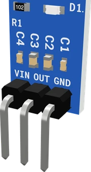
The AMS1117-3.3 module is a small breakout around AMS's AMS1117-3.3 low-dropout regulator, a 1 A part whose dropout is 1.1 V typical and 1.3 V maximum at 0.8 A (AMS1117 datasheet, pp. 1, 3). Wire a 5 V supply to VIN, ground to GND, and take 3.3 V from OUT for your 3.3 V parts; the chip's absolute maximum input is 15 V (p. 2). The module already carries the output capacitor the regulator needs for stability (p. 4).
The AMS1117-3.3 module is one of the most common ways to get 3.3 V on a breadboard. It is a small blue board with a three-pin header, VIN, GND and OUT, carrying an AMS1117-3.3 regulator in a SOT-223 package, its input and output capacitors and a red power LED. Several makers build it to the same pattern; the regulator itself is Advanced Monolithic Systems' AMS1117.
The AMS1117 is a three-terminal low-dropout linear regulator rated for up to 1 A. The 3.3 V version holds 3.251 V to 3.349 V at 4.8 V in, its dropout is 1.1 V typical and 1.3 V maximum at 0.8 A, and it includes current limiting (900 mA minimum, 1.1 A typical) and thermal shutdown at a 165 °C junction (AMS1117 datasheet, pp. 2, 3, 4). In practice that means a 5 V USB rail or an Arduino's 5V pin is enough to run it.
Being linear, it turns the dropped voltage into heat: (VIN minus 3.3 V) times the load current. AMS guarantees its regulation specs up to 1.2 W of dissipation in the SOT-223 package (p. 3), which is about 700 mA from 5 V but only about 140 mA from 12 V. It is the right part for a few hundred milliamps of 3.3 V from 5 V; for big drops at high current, a buck converter wastes far less.
AMS1117 3.3V Regulator Module pinout
| Pin | Function | Type |
|---|---|---|
| VIN | VIN (4.5-12 V in)3.3 V (max 12 V) | power in |
| OUT | OUT (3.3 V) | power out |
| GND | GND | power in |
How to wire the AMS1117 3.3V Regulator Module
Pin by pin, for the board you have.
| AMS1117 3.3V Regulator Module | Arduino Uno | Note |
|---|---|---|
| VIN | 5V | |
| GND | GND |
| AMS1117 3.3V Regulator Module | ESP32 DevKit V1 | Note |
|---|---|---|
| VIN | VIN | |
| GND | GND |
- VIN is on VIN, which gives about 5 V only while the board is powered from USB.
| AMS1117 3.3V Regulator Module | Raspberry Pi Pico | Note |
|---|---|---|
| VIN | VBUS | |
| GND | GND |
- VIN is on VBUS, which gives about 5 V only while the board is powered from USB.
Before you wire it
- GND to the circuit's ground, shared with the board that talks to the 3.3 V part.
- OUT feeds only 3.3 V parts: wire their VCC to OUT (or put OUT on a rail of its own and say which rail is 3.3 V). Never tie OUT to a rail another supply drives.
- The supply goes to VIN, never to OUT: fed through OUT it regulates nothing.
- Heat: the regulator burns (VIN − 3.3 V) x current.
- A board's logic pins still talk to the 3.3 V part: a 5 V board's outputs into a 3.3 V-only input need a level shifter or a divider (say so).
- From 5 V keep the load to about 700 mA: the SOT-223 package limits the regulator to 1.2 W
- No VIN from a 3.3 V source; NO VIN above 12 V (15 V destroys it).
- No OUT on a 5 V rail or a board's 5V pin.
- Feed VIN from a supply above about 4.6 V so the 3.3 V output stays in regulation through the 1.3 V maximum dropout (AMS1117 datasheet, p. 3): a USB 5 V rail, an Arduino's 5V or VIN pin, a 4xAA pack or a 9 V battery. Never exceed the 15 V absolute maximum (p. 2).
- Keep the dissipation, (VIN minus 3.3 V) times the current, within the 1.2 W AMS guarantees for SOT-223 (p. 3): roughly 700 mA from 5 V, 200 mA from 9 V and 140 mA from 12 V. The module's small copper area sits at the high end of the 46 to 90 °C/W range (p. 2), so it runs hot near those limits.
- Share GND between the module, the supply and the microcontroller. OUT feeds only 3.3 V parts; never connect OUT to a rail another supply drives.
- The regulator powers 3.3 V parts but does not translate logic levels. A 5 V board's output into a 3.3 V-only input still needs a divider or a level shifter.
- The module's own capacitors cover the regulator's stability. AMS notes that 22 µF of tantalum on the output ensures stability in all conditions (p. 4); add bulk capacitance at a load with large current spikes, such as an ESP8266 or an nRF24L01.
Specifications
- Output voltage (chip)
- 3.3 V; 3.251 V to 3.349 V at VIN 4.8 V, 25 °CAMS1117 datasheet (Advanced Monolithic Systems), p. 2
- Output current (chip)
- Up to 1 AAMS1117 datasheet, p. 1
- Dropout voltage
- 1.1 V typical, 1.3 V max at 0.8 AAMS1117 datasheet, p. 3
- Input voltage
- 15 V absolute maximumAMS1117 datasheet, p. 2
- Current limit
- 900 mA min, 1100 mA typical, 1500 mA maxAMS1117 datasheet, p. 3
- Quiescent current
- 5 mA typical, 11 mA maxAMS1117 datasheet, p. 3
- Dissipation for guaranteed regulation
- 1.2 W in SOT-223AMS1117 datasheet, p. 3 (note 2)
- SOT-223 thermal resistance
- 90 °C/W, 46 °C/W to over 90 °C/W depending on copper areaAMS1117 datasheet, p. 2
- Thermal shutdown
- Junction above 165 °CAMS1117 datasheet, p. 4
- Module pins
- VIN, GND, OUT (3.3 V)Tinkered component registry
- Maximum supply voltage
- 12 V
- Dimensions
- 8.8 × 7.6 × 17.9 mm
- Weight
- 1 g
- Output voltage
- 3.3 Vmaker's datasheet, checked 29 Oct 2026
- Output current
- 1 A, limited to 1.2 W in SOT-223 (about 700 mA from 5 V)maker's datasheet, checked 29 Oct 2026
From the Generic (AMS AMS1117-3.3)'s datasheet, published by Generic (AMS AMS1117-3.3).
Common mistakes
Powering it from 3.3 V or a single Li-ion cell
With up to 1.3 V of dropout at 0.8 A (AMS1117 datasheet, p. 3), the output falls well below 3.3 V from a 3.3 V or 3.7 V source. Feed it 5 V, or choose a lower-dropout regulator for a single cell.
Expecting a full 1 A from 12 V
From 12 V the regulator burns 8.7 V times the current: 1 A would be 8.7 W, far above the 1.2 W AMS guarantees for SOT-223 (p. 3). Above about 140 mA from 12 V it overheats and the thermal shutdown cuts in; use a buck converter instead.
Wiring the supply to OUT
VIN is the input and OUT the 3.3 V output. Feeding the supply into OUT bypasses the regulator, and a 5 V supply then reaches every 3.3 V part on the rail.
Assuming it level-shifts signals
The module only supplies power. A 5 V microcontroller's TX or SPI lines still swing to 5 V and need a divider or level shifter before a 3.3 V-only input.
Forgetting a common ground
If the module's GND is not tied to the microcontroller's GND, the 3.3 V part and the board have no shared reference and communication fails.
AMS1117 3.3V Regulator Module questions
How do I wire an AMS1117 3.3 V module to an Arduino?
Connect the Arduino's 5V pin to VIN and GND to GND, then take 3.3 V from OUT to your 3.3 V module's VCC. At 5 V in, the AMS1117-3.3 has headroom over its 1.3 V maximum dropout (AMS1117 datasheet, p. 3) and can supply several hundred milliamps.
What is the maximum input voltage of the AMS1117-3.3?
The chip's absolute maximum input is 15 V (AMS1117 datasheet, p. 2). Above about 9 V the heat limit, 1.2 W for guaranteed regulation in SOT-223 (p. 3), restricts the current far more than the voltage rating does.
How much current can the AMS1117 3.3 V module supply?
The chip is rated for 1 A with a current limit of 900 mA minimum (AMS1117 datasheet, pp. 1, 3), but heat sets the real limit: about 700 mA from 5 V and about 140 mA from 12 V before passing the 1.2 W AMS guarantees for SOT-223 (p. 3).
Can I run an ESP8266 or ESP-01 from an AMS1117 module?
Yes, from 5 V in. The module gives enough current for the Wi-Fi bursts, and its output stays at 3.3 V while the input is above about 4.6 V (AMS1117 datasheet, p. 3). Add a bulk capacitor beside the ESP for its current spikes.
My AMS1117 module's output is low or it gets very hot. Why?
A low output means the input is too close to 3.3 V: it needs 1.1 V to 1.3 V of headroom at load (AMS1117 datasheet, p. 3). Heat means the dissipation, (VIN minus 3.3 V) times the current, is high; past 165 °C the thermal shutdown turns it off (p. 4). Lower the input voltage or the load, or use a buck converter.
AMS1117 vs LM1117: are they interchangeable?
Mostly. Both are 1117-style LDOs with the same GND/ADJ, VOUT, VIN pinout. AMS's AMS1117 is rated for 1 A (AMS1117 datasheet, p. 1); TI's LM1117 for 800 mA and a 15 V recommended input (TI LM1117 datasheet, pp. 1, 4). The module saves you fitting the capacitors yourself.
Build something with the AMS1117 3.3V Regulator Module
3.3 V rail for an Arduino Uno
Power an nRF24L01, RC522 RFID reader or 3.3 V sensor from the Uno's 5V pin.
ESP-01 adapter
Run an ESP-01 or ESP8266 module from a 5 V USB supply with a steady 3.3 V.
Breadboard 3.3 V supply
Turn a USB charger or 4xAA pack into a 3.3 V breadboard rail for low-power circuits.
Mixed 5 V and 3.3 V builds
Keep motors and 5 V modules on the main rail while the module feeds the 3.3 V sensors.
This page as plain Markdown, for ChatGPT, Claude or your own agent. /components/ams1117-3v3-module.md