LM1117 3.3V Regulator (TO-220)
TI's 800 mA low-dropout regulator in TO-220: a fixed 3.3 V from a 5 V or higher supply, with about 1.2 V of dropout.
- Output voltage3.3 V (3.267 V to 3.333 V at 10 mA, 25 °C)
- Output current800 mA
- Dropout voltage1.1 V at 100 mA, 1.15 V at 500 mA, 1.2 V at 800 mA (typical)
- Input voltage15 V max recommended; 20 V absolute maximum
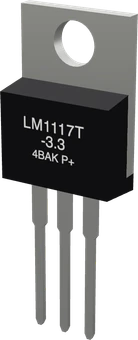
The LM1117T-3.3 is a 3.3 V low-dropout linear regulator in a TO-220 package that delivers up to 800 mA with a typical dropout of 1.2 V at full load (TI LM1117 datasheet, p. 1). Looking at its front, pin 1 is GND, pin 2 (and the tab) is the 3.3 V output, pin 3 is the input, which takes up to 15 V (pp. 3, 4). Put a 10 µF capacitor on the output, required for stability, and another on the input (pp. 14, 15).
The LM1117 is a three-terminal low-dropout (LDO) linear regulator from Texas Instruments, made in adjustable and fixed 1.8 V, 2.5 V, 3.3 V and 5 V versions. The LM1117T-3.3 is the fixed 3.3 V version in the through-hole TO-220 package, which stands in a breadboard and bolts to a heatsink (TI LM1117 datasheet, pp. 1, 3).
It drops a higher voltage to a steady 3.3 V for up to 800 mA. Its dropout is 1.2 V typical at 800 mA, 1.1 V at 100 mA, so a 5 V USB rail or Arduino 5V pin is enough to run it; TI specifies the 3.3 V output from 4.75 V to 10 V in, and the input may go up to 15 V (pp. 4, 5, 6). Inside are current limiting at 1.2 A typical and thermal shutdown (pp. 1, 6).
Unlike a ready-made AMS1117 module, the bare LM1117 has no capacitors of its own. TI requires at least 10 µF on the output, a tantalum with an ESR between 0.3 Ω and 22 Ω, to keep the regulator stable, and recommends 10 µF on the input (pp. 14, 15). It is a linear regulator, so every volt it drops at the load current turns into heat in its tab.
LM1117 3.3V Regulator (TO-220) pinout
| Pin | Function | Type |
|---|---|---|
| GND | 1 GND (ADJ/GND) | power in |
| OUT | 2 VOUT (3.3 V, also the tab) | power out |
| IN | 3 VIN (4.5-15 V)3.3 V (max 15 V) | power in |
How to wire the LM1117 3.3V Regulator (TO-220)
Pin by pin, for the board you have.
| LM1117 3.3V Regulator (TO-220) | Arduino Uno | Note |
|---|---|---|
| IN | 5V | |
| GND | GND |
| LM1117 3.3V Regulator (TO-220) | ESP32 DevKit V1 | Note |
|---|---|---|
| IN | VIN | |
| GND | GND |
- IN is on VIN, which gives about 5 V only while the board is powered from USB.
| LM1117 3.3V Regulator (TO-220) | Raspberry Pi Pico | Note |
|---|---|---|
| IN | VBUS | |
| GND | GND |
- IN is on VBUS, which gives about 5 V only while the board is powered from USB.
Before you wire it
- A 10 µF capacitor from OUT to GND (and one from IN to GND): TI's datasheet requires the output one for stability; without it the regulator can oscillate.
- IN 4.75-10 V, from a supply: a board's 5V or VIN pin, a 5 V rail (an MB102 side at 5 V), a 9 V battery, a 4xAA pack.
- GND to the circuit's ground, shared with the board that talks to the 3.3 V part.
- OUT feeds only 3.3 V parts. The tab is OUT too: nothing metal may touch it.
- The supply goes to IN (pin 3), never to OUT: fed through OUT it regulates nothing.
- Prefer the AMS1117 module when the user just needs 3.3 V on a breadboard (capacitors on board, fewer parts); use the LM1117 when they ask for it, or to learn how a bare regulator is wired.
- No LM1117 without its output capacitor.
- No IN above 15 V; NO OUT on a 5 V rail or a board's 5V pin.
- No swapping the pins: pin 1 is GND, not IN (unlike the 7805's IN-GND-OUT).
- Pin order is GND, OUT, IN from left to right on the front, not the IN, GND, OUT of a 7805, and the metal tab is the output (TI datasheet, p. 3). Keep the tab away from other metal or insulate it on a heatsink.
- Fit at least 10 µF from OUT to GND, close to the pins. TI asks for a tantalum with an ESR of 0.3 Ω to 22 Ω; more capacitance only improves stability (p. 15). A 10 µF capacitor on IN is recommended too (p. 14).
- Feed IN from 4.75 V up to 15 V for a fully specified 3.3 V output (pp. 4, 5): a 5 V rail, an Arduino's 5V or VIN pin, a 9 V battery or a 12 V adapter. From a 3.3 V or 3.7 V source the output follows the input minus the dropout and sags.
- Heat is (VIN minus 3.3 V) times the load current, plus VIN times the 5 mA ground current (p. 18). From 5 V at 500 mA it dissipates about 0.9 W; from 12 V at the same current, about 4.4 W, which needs a heatsink. The junction must stay under 125 °C, and thermal shutdown cuts the output if it does not.
- Share the regulator's GND with the microcontroller that talks to the 3.3 V part, and feed only 3.3 V parts from OUT.
Specifications
- Output voltage
- 3.3 V (3.267 V to 3.333 V at 10 mA, 25 °C)TI LM1117 datasheet (SNOS412Q), p. 5
- Output current
- 800 mATI LM1117 datasheet, p. 1
- Dropout voltage
- 1.1 V at 100 mA, 1.15 V at 500 mA, 1.2 V at 800 mA (typical)TI LM1117 datasheet, p. 6
- Input voltage
- 15 V max recommended; 20 V absolute maximumTI LM1117 datasheet, p. 4
- Current limit
- 800 mA min, 1200 mA typical, 1500 mA maxTI LM1117 datasheet, p. 6
- Quiescent current
- 5 mA typical, 10 mA maxTI LM1117 datasheet, p. 6
- Output capacitor
- 10 µF minimum (tantalum), ESR 0.3 Ω to 22 ΩTI LM1117 datasheet, p. 15
- TO-220 pinout
- 1 ADJ/GND, 2 VOUT (and tab), 3 VINTI LM1117 datasheet, p. 3
- Junction temperature
- 0 °C to 125 °C (LM1117); thermal shutdown built inTI LM1117 datasheet, pp. 4, 18
- Dimensions
- 10.16 × 4.57 × 28.7 mm
- Weight
- 2 g
From the Texas Instruments's datasheet, published by Texas Instruments.
Common mistakes
Wiring it like a 7805
The 7805 is IN, GND, OUT; the LM1117 is GND, OUT, IN (TI datasheet, p. 3). Swapping them feeds the supply into the output or ground and the part regulates nothing.
Leaving out the output capacitor
The LM1117 needs at least 10 µF on its output, with an ESR between 0.3 Ω and 22 Ω, to stay stable (p. 15). Without it the output can oscillate and devices on the 3.3 V rail reset at random.
Using only a tiny ceramic on the output
A small multilayer ceramic alone can have an ESR below the 0.3 Ω TI asks for (p. 15). Use a 10 µF tantalum, or an electrolytic of 10 µF or more, as the output capacitor.
Feeding it from 3.3 V or a single Li-ion cell
With about 1.2 V of dropout at 800 mA (p. 6), the output cannot reach 3.3 V from a 3.3 V or 3.7 V source. Use 4.75 V or more in, or a lower-dropout regulator.
Pulling high current from 12 V without a heatsink
All of the 8.7 V dropped from 12 V to 3.3 V turns into heat. At a few hundred milliamps that is several watts, enough to trip the thermal shutdown (p. 18). Add a heatsink or use a buck converter.
LM1117 3.3V Regulator (TO-220) questions
What is the LM1117T-3.3 pinout?
Facing the printed side with the leads down: pin 1 is ADJ/GND, pin 2 is VOUT (3.3 V) and pin 3 is VIN. The metal tab is also VOUT (TI LM1117 datasheet, p. 3).
What input voltage does the LM1117 3.3 V need?
TI specifies the 3.3 V output from 4.75 V to 10 V in across the full load range, and the input may go up to 15 V (datasheet, pp. 4, 5). The absolute maximum is 20 V. Below about 4.5 V the output drops with the input.
Can I power an ESP8266 or ESP32 from an LM1117 3.3 V?
Yes, from 5 V in. It delivers up to 800 mA (datasheet, p. 1), enough for the Wi-Fi bursts, as long as the 10 µF output capacitor is fitted and the input is 4.75 V or more. Add extra bulk capacitance near the module for its current spikes.
Why is my LM1117 getting hot or its output oscillating?
Hot: it burns (VIN minus 3.3 V) times the current (datasheet, p. 18), so a high input voltage at a large load needs a heatsink or a buck converter. Oscillating or noisy: check the output capacitor, at least 10 µF with an ESR of 0.3 Ω to 22 Ω, placed close to the pins (p. 15).
LM1117 vs AMS1117: what is the difference?
They share the 1117 pinout and job. TI's LM1117 is rated for 800 mA and 15 V of recommended input (TI datasheet, pp. 1, 4); AMS's AMS1117 is rated for 1 A with a 15 V absolute maximum input (AMS1117 datasheet, pp. 1, 2). Both need an output capacitor; small AMS1117 modules come with theirs fitted.
LM1117 vs a buck converter like the LM2596?
The LM1117 is simple, quiet and cheap, but wastes the dropped voltage as heat. A buck converter switches instead: TI's LM2596 reaches 73 % to 90 % efficiency at 3 A in its datasheet's test circuits (LM2596 datasheet, p. 6). For large drops at high current, use a buck.
Build something with the LM1117 3.3V Regulator (TO-220)
3.3 V rail from a 5 V Arduino
Power an nRF24L01, RC522 RFID reader or a 3.3 V sensor from the Uno's 5V pin with more current than its 3V3 pin gives.
ESP8266 or ESP-01 power supply
Give an ESP module a steady 3.3 V from USB 5 V, with a bulk capacitor for its Wi-Fi bursts.
Breadboard power rail
Build a 3.3 V rail on a breadboard from a 9 V battery or 12 V adapter, with input and output capacitors.
Learning linear regulation
Measure dropout and heat at different loads to see why LDOs need headroom and a heatsink.
This page as plain Markdown, for ChatGPT, Claude or your own agent. /components/lm1117t-3v3.md