Electrolytic Capacitor (470µF)
A polarised 470 µF, 25 V aluminium electrolytic capacitor: the bulk reservoir that stops motor, servo and LED supplies from sagging.
- Capacitance470 µF ±20% (at 120 Hz, 20 °C)
- Rated voltage25 V DC (peak of DC plus ripple must stay under it)
- Case size (UPW1E471MPD)Ø10 × 16 mm, lead spacing 5.0 mm, lead Ø0.6 mm
- Rated ripple current1050 mA rms at 105 °C, 100 kHz (× 0.75 at 120 Hz)
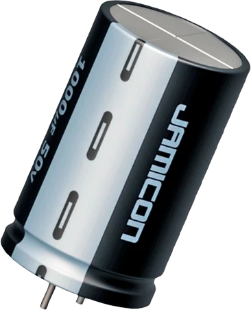
A 470 µF electrolytic is a polarised bulk capacitor: Nichicon's 25 V version in a 10 × 16 mm can holds 470 µF ±20% and handles 1050 mA rms of ripple at 105 °C, 100 kHz (Nichicon UPW datasheet, pp. 1, 3). Connect the plus lead to the supply rail and the striped minus lead to GND, close to the load it feeds, and keep the peak voltage, DC plus ripple, under the 25 V rating (Nichicon Technical Notes CAT.8101C, p. 1). Never reverse it or put it across AC.
An aluminium electrolytic capacitor stores far more charge for its size than a ceramic, which is why it is the black or blue can found across the supply of nearly every motor driver, servo board and LED strip. A 470 µF part is the common middle value: large enough to cover the current spikes of a stepper driver, a servo or a few dozen addressable LEDs, small enough to sit on a breadboard. The representative part here is Nichicon's UPW1E471MPD: 470 µF, 25 V, in a 10 mm by 16 mm can with leads 5.0 mm apart (Nichicon UPW datasheet, pp. 1, 3).
It is polarised. The electrolyte and oxide layer only work one way round, so the positive lead goes to the more positive node and the negative lead, marked by the stripe on the sleeve, goes to ground. Nichicon is blunt about it: do not apply reverse voltage or AC voltage, and use a bipolar capacitor in any circuit that can see reversed polarity (Technical Notes CAT.8101C, p. 1). A reversed part heats, builds internal gas and opens its pressure relief vent.
The page covers the whole family of stocked values, from 1 µF to 2200 µF. Capacitance and voltage both cost volume, so larger values ship at lower ratings or in bigger cans: in Nichicon's general-purpose VR series, 25 V parts grow from 8 × 11.5 mm at 220 µF to 10 × 20 mm at 1000 µF, and a 16 V 2200 µF part needs a 12.5 × 20 mm can (Nichicon UVR datasheet, p. 2). Pair every bulk electrolytic with a 100 nF ceramic: the electrolytic covers the slow sag, the ceramic the fast edges.
Before you wire it
- POLARITY. This is the one that destroys hardware. pin1 is the anode (+), pin2 is the cathode (-): the lead on the striped side of the can, and the shorter of the two. Anode goes to the more positive node, cathode to the more negative one, always. An aluminium electrolytic has no reverse withstand rating: reverse voltage vents it in seconds. Wiring it backwards is a blocking validation error, not a warning.
- Voltage rating. Each value ships at a real rating (see the table). Pick a part rated at least 1.5x the rail it sits on, and never run one above 80% of its rating. On a 12 V motor supply that means a 25 V part, not a 16 V one.
- Never across an AC or a reversing node. An H-bridge output, a transformer secondary, or any pin that swings below its neighbour needs a non-polarised part. Put the electrolytic on the SUPPLY side of the driver, never on the motor terminals.
- Breadboard placement: stay in the same bank (a-e or f-j), never bridge the centre gap. The lead pitch grows with the can, so the two pins land 1 row apart up to 47 uF, 2 rows apart at 100-680 uF, and 3 rows apart at 1000 uF and above. Placement handles the spacing; you only choose the start row.
- No reversed polarity. Anode (+) to the positive node, cathode (-) to GND or the more negative node.
- No electrolytic in series with a signal that swings both ways, and none across a motor's own terminals.
- No electrolytic as the decoupling cap at an IC's power pins: it is too slow and too far away. That is the ceramic's job.
- No part whose rating is below the rail it sits on.
- No placing both pins in the same row and bank (that is a short), and no bridging the centre gap.
- Polarity first: plus to the supply rail, the striped minus lead to GND or the more negative node. Nichicon forbids reverse and AC voltage on any aluminium electrolytic (Technical Notes CAT.8101C, p. 1).
- Pick a rating with margin over the rail. Nichicon's rule is that the peak voltage, DC plus ripple, must never exceed the rated voltage (CAT.8101C, p. 1); a 25 V part is the right choice on a 12 V motor supply, a 16 V part is not.
- Place it at the point of load: across the VIN and GND terminals of a motor driver, servo header or LED strip, with short leads. Adafruit recommends 500 to 1000 µF at 6.3 V or higher across an addressable LED strip's supply (Adafruit NeoPixel Überguide, Best Practices).
- Put it on the supply side of an H-bridge, never across the motor terminals, which swing both ways.
- Keep a ceramic beside it: an electrolytic is too slow for an IC's power pins, so each chip still gets its own 100 nF ceramic.
- Leave room above the vent: Nichicon asks for 2 mm or more of clearance above the pressure relief vent on cans from Ø6.3 to 16 mm (CAT.8101C, p. 1).
- Heat shortens its life. Below the maximum operating temperature, life roughly halves for each 10 °C rise (CAT.8101C, section 2-9-3), so keep it away from regulators and heatsinks.
Electrolytic Capacitor (470µF) variants
The same part in the values and versions the studio carries.
| Variant | Capacitance | Voltage rating |
|---|---|---|
| Electrolytic Capacitor (1µF) | 1 µF | 50 V |
| Electrolytic Capacitor (10µF) | 10 µF | 50 V |
| Electrolytic Capacitor (22µF) | 22 µF | 50 V |
| Electrolytic Capacitor (47µF) | 47 µF | 50 V |
| Electrolytic Capacitor (100µF) | 100 µF | 25 V |
| Electrolytic Capacitor (220µF) | 220 µF | 25 V |
| Electrolytic Capacitor (470µF) | 470 µF | 25 V |
| Electrolytic Capacitor (1000µF) | 1000 µF | 25 V |
| Electrolytic Capacitor (2200µF) | 2200 µF | 16 V |
Specifications
- Capacitance
- 470 µF ±20% (at 120 Hz, 20 °C)Nichicon UPW datasheet CAT.8100N, pp. 1, 3
- Rated voltage
- 25 V DC (peak of DC plus ripple must stay under it)Nichicon UPW datasheet, p. 3; Technical Notes CAT.8101C, p. 1
- Case size (UPW1E471MPD)
- Ø10 × 16 mm, lead spacing 5.0 mm, lead Ø0.6 mmNichicon UPW datasheet, pp. 1, 3
- Rated ripple current
- 1050 mA rms at 105 °C, 100 kHz (× 0.75 at 120 Hz)Nichicon UPW datasheet, pp. 1, 3
- Impedance, max.
- 0.068 Ω at 20 °C and 0.136 Ω at -10 °C, 100 kHzNichicon UPW datasheet, p. 3
- Leakage current, max.
- 352.5 µA (0.03CV) after 1 minute at rated voltageNichicon UPW datasheet, pp. 1, 3
- Dissipation factor (tan δ)
- 0.14 max. at 120 HzNichicon UPW datasheet, p. 1
- Category temperature range
- -55 °C to +105 °CNichicon UPW datasheet, p. 1
- Endurance
- 5000 hours at 105 °C with rated ripple (Ø10 mm case)Nichicon UPW datasheet, p. 1
- Life versus temperature
- Roughly doubles for each 10 °C cooler below the maximumNichicon Technical Notes CAT.8101C, section 2-9-3
- Maximum supply voltage
- 25 V
- Dimensions
- 10 × 10 × 16 mm
Common mistakes
Fitting it backwards
The stripe marks the negative lead. Reversed, the capacitor conducts, heats and can vent within seconds; Nichicon lists reverse voltage among the causes of vent operation (Technical Notes CAT.8101C). Check the stripe against GND before power goes on.
A voltage rating too close to the rail
A 16 V can on a 12 V motor supply leaves little room for the spikes motors and long leads add. The peak, DC plus ripple, must stay under the rating (CAT.8101C, p. 1); choose 25 V for 12 V and 16 V or more for 5 V.
Using it across a motor or any AC node
An H-bridge output or a transformer secondary reverses polarity every cycle. Nichicon says even bipolar electrolytics cannot be used for AC (CAT.8101C, p. 1). Put the electrolytic on the driver's supply and use a ceramic across the motor if it needs one.
Treating it as an IC's decoupling capacitor
A large can far from a chip does not supply the fast current edges a microcontroller draws. Keep a 100 nF ceramic at each IC's power pins and use the electrolytic as the rail's bulk reservoir.
Both leads in the same breadboard row
The 5.0 mm lead spacing of a 10 mm can (Nichicon UPW datasheet, p. 1) lands the leads two holes apart. Put them in two different rows of the same side, never in one row, which shorts the capacitor.
Electrolytic Capacitor (470µF) questions
Which leg of an electrolytic capacitor is positive?
The negative lead is the one on the side of the sleeve's stripe, usually printed with minus signs; the other lead is positive. On a new part with uncut leads the negative lead is also the shorter one. Nichicon asks you to confirm polarity before installing (Technical Notes CAT.8101C).
What voltage rating do I need for a 470 µF capacitor?
A rating above the highest peak the rail reaches, DC plus ripple, since the peak must never exceed the rated voltage (CAT.8101C, p. 1). In practice that is 16 V or 25 V on a 5 V rail and 25 V on a 12 V rail. A higher rating is never a problem except for size.
Can I use a 470 µF capacitor with an ESP32 or other 3.3 V board?
Yes. A 25 V part works on any lower rail, 3.3 V and 5 V included, since the rating is a maximum. Makers often add one across the 3V3 and GND pins of an ESP32 board to ride out the current bursts of Wi-Fi transmission; plus to 3V3, stripe to GND.
What happens if I connect an electrolytic capacitor backwards?
It passes current, heats up and generates gas until the pressure relief vent opens, sometimes with a pop and leaking electrolyte; Nichicon lists reverse voltage as a cause of vent operation (CAT.8101C). Replace any capacitor that was reversed, even if it looks intact.
Do I need a capacitor for a NeoPixel strip or servos?
Yes for anything beyond a few pixels or one small servo. Adafruit recommends 500 to 1000 µF at 6.3 V or higher across the strip's + and - terminals to buffer sudden current changes (NeoPixel Überguide, Best Practices). A 470 µF to 1000 µF can across a servo supply does the same job.
Electrolytic vs ceramic capacitor: which should I use?
Both, for different jobs. The electrolytic gives bulk capacitance, hundreds of µF in a 10 × 16 mm can (Nichicon UPW datasheet, p. 3), for slow supply sag; a 100 nF ceramic handles the fast edges at each IC and is not polarised. Use ceramics at chip pins and electrolytics where a rail feeds motors, servos or LEDs.
How long does an electrolytic capacitor last?
Nichicon rates the PW series in a 10 mm can for 5000 hours at 105 °C with full ripple (UPW datasheet, p. 1), and life roughly doubles for each 10 °C cooler (Technical Notes CAT.8101C, section 2-9-3). Kept well below its maximum temperature, it lasts many years.
Build something with the Electrolytic Capacitor (470µF)
Motor driver bulk supply
Sit a 470 µF can across the VM and GND terminals of an L298N, TB6612, A4988 or TMC2209 to absorb the current spikes of each step or PWM edge.
Servo power rail
Hold a servo rail steady so a starting servo does not brown out the microcontroller sharing its supply.
Addressable LED strip
Buffer the strip's supply as Adafruit recommends before connecting a large power source to NeoPixels.
Brownout fix for Wi-Fi boards
Add a bulk capacitor across 3V3 and GND on an ESP32 or ESP8266 board that resets when its radio transmits.
NE555 long timer
Use a large electrolytic as the timing capacitor for delays of seconds to minutes, minus lead to GND.
This page as plain Markdown, for ChatGPT, Claude or your own agent. /components/capacitor-electrolytic-470uf.md