L298N Motor Driver with an ESP32 DevKit V1
Dual full-bridge (H-bridge) driver built on the STMicroelectronics L298 IC that lets a microcontroller run two DC motors or one bipolar stepper at up to 2A per channel.
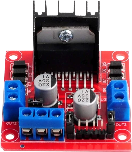
With an ESP32 DevKit V1 the L298N's 5V logic pin goes to VIN, and its IN and EN pins take the ESP32's 3.3 V outputs directly because the L298 reads 2.3 V as a high. ENA is on GPIO4 and ENB on GPIO16 for PWM speed, with IN1 to IN4 on GPIO13, 14, 27 and 26.
Wiring the L298N Motor Driver to the ESP32 DevKit V1
Pin by pin.
| L298N Motor Driver | ESP32 DevKit V1 | Note |
|---|---|---|
| IN1 | GPIO13 (D13) | |
| IN2 | GPIO14 (D14) | |
| ENA | GPIO4 (D4) | |
| IN3 | GPIO27 (D27) | |
| IN4 | GPIO26 (D26) | |
| ENB | GPIO16 (RX2) | |
| 5V | VIN | only with the module's 5V-EN jumper removed. With the jumper fitted (motor supply 12 V or less) its regulator makes 5 V on this pin: leave this wire off, or two supplies fight |
| GND | GND | |
| VMS | a separate motor supply, its − to GND |
- 5V is on VIN, which gives about 5 V only while the board is powered from USB.
What to know on the ESP32 DevKit V1
- The logic supply is rated 4.5 V to 7 V, so it cannot run from the 3V3 pin. VIN gives about 5 V only on USB; the logic draws 24 mA typical, 36 mA maximum. Remove the module's 5V-enable jumper first, or its onboard regulator and VIN drive the same pin.ST L298 datasheet, p. 3
- analogWrite() on ENA and ENB uses the ESP32's LED PWM controller. If you raise the PWM frequency, stay within the L298's 40 kHz maximum switching frequency.Espressif ESP32 Series Datasheet v5.3, p. 39; ST L298 datasheet, p. 4
- ENB sits on GPIO16, which the DevKit labels RX2. That is fine for PWM, but do not start Serial2 on its default pins in the same sketch.arduino-esp32 core, HardwareSerial default pins for Serial2 (RX2 GPIO16, TX2 GPIO17)
- Budget for the bridge's loss when choosing the motor supply: 1.8 V to 3.2 V drop at 1 A. The ESP32 changes nothing here; the motors still need their own supply on VMS with a shared ground.ST L298 datasheet, p. 3
L298N Motor Driver code for the ESP32 DevKit V1
Compiled for esp32:esp32:esp32 on 2026-10-29.
// L298N Motor Driver on ESP32 DevKit V1: wiring and a free simulation at https://www.tinkered.ai/components/l298n-stepper-driver/esp32
const int IN1 = 13, IN2 = 14, ENA = 4;    // channel A
const int IN3 = 27, IN4 = 26, ENB = 16;   // channel B

void setup() {
  const int pins[] = {IN1, IN2, ENA, IN3, IN4, ENB};   // an array: AVR has no <initializer_list>
  for (int p : pins) pinMode(p, OUTPUT);
}

// speed: -255..255, sign is direction
void driveA(int speed) {
  digitalWrite(IN1, speed >= 0);
  digitalWrite(IN2, speed < 0);
  analogWrite(ENA, abs(speed));
}

void loop() {
  driveA(200);   delay(2000);   // forward
  driveA(0);     delay(1000);   // stop
  driveA(-200);  delay(2000);   // reverse
  driveA(0);     delay(1000);
}
L298N Motor Driver on the ESP32 DevKit V1: questions
Do I need a level shifter between the ESP32 and the L298N?
No. Input and enable high level is 2.3 V minimum (ST datasheet, p. 3), below the ESP32's 3.3 V outputs. Only the module's 5V logic supply needs 5 V.
Which ESP32 pins can do PWM for ENA and ENB?
Any output-capable GPIO: the LED PWM controller routes to any of them (ESP32 datasheet, p. 39). Avoid the input-only GPIO34 to GPIO39 and the strapping pins GPIO0, 2, 5, 12 and 15.
Keep going
This guide as plain Markdown. /components/l298n-stepper-driver/esp32.md