TB6612FNG vs L298N
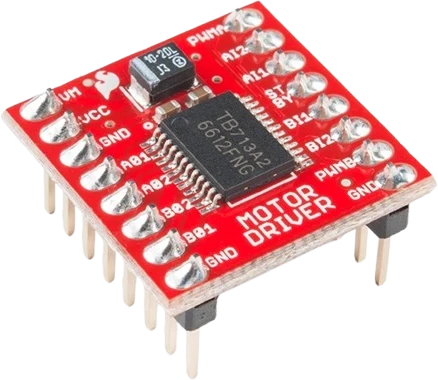
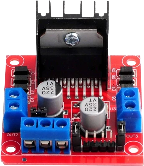
For motors up to 13.5 V and 1 A per channel the TB6612FNG wins: its MOSFET bridge loses 0.5 V typical at 1 A across both switches (Toshiba TB6612FNG datasheet, pp. 1, 5), where the L298's bipolar bridge loses 1.8 V to 3.2 V at the same current (ST L298 datasheet, p. 3). The L298N still covers what the TB6612FNG cannot: 2 A DC per channel and motor supplies up to 46 V on the chip, 35 V on the module (ST, pp. 2, 3; Handson L298N user guide, p. 1).
Side by side
| TB6612FNG | L298N | |
|---|---|---|
| Output transistorsToshiba TB6612FNG datasheet, p. 1; ST L298 datasheet, p. 1 | LD-MOS (MOSFET) | Bipolar |
| Current per channelToshiba TB6612FNG datasheet, pp. 1 to 3; ST L298 datasheet, p. 2 | 1.0 A recommended, 1.2 A average max, 3.2 A single 10 ms pulse | 2 A DC, 2.5 A repetitive peak, 3 A for 100 µs |
| Voltage lost in the bridgeToshiba TB6612FNG datasheet, p. 5; ST L298 datasheet, p. 3 | 0.5 V typ at 1 A (upper plus lower switch) | 1.8 V to 3.2 V at 1 A, up to 4.9 V at 2 A |
| Motor supplyToshiba TB6612FNG datasheet, pp. 2, 3; ST L298 datasheet, p. 3; Handson L298N user guide, p. 1 | 2.5 V to 13.5 V (15 V absolute max) | Up to 46 V on the L298; 5 V to 35 V on the module |
| Logic supplyToshiba TB6612FNG datasheet, p. 3; ST L298 datasheet, p. 3 | 2.7 V to 5.5 V on VCC | 4.5 V to 7 V on VSS, or the module's 5 V regulator |
| Flyback diodesToshiba TB6612FNG datasheet, p. 5; ST L298 datasheet, p. 7 | Built in (regenerative diodes) | None in the chip; the module carries them |
| StandbyToshiba TB6612FNG datasheet, p. 5; ST L298 datasheet, p. 3 | STBY pin, 1 µA max from each supply | No standby; 24 mA typ logic current |
| PWM frequencyToshiba TB6612FNG datasheet, p. 3; ST L298 datasheet, p. 4 | Up to 100 kHz | 25 kHz typ, 40 kHz max |
| ProtectionToshiba TB6612FNG datasheet, pp. 1, 5; ST L298 datasheet, pp. 1, 3 | Thermal shutdown (175 °C design value), low-voltage detection | Sense pins for an external current resistor; heatsink on the module |
Which one to pick
- Battery robots with 4.5 V to 12 V gear motors: half a volt lost at 1 A leaves the motor nearly the whole battery (Toshiba datasheet, p. 5). Below 4.5 V on VM, Toshiba rates it for less current per channel.
- 3.3 V boards powering the logic from their own 3V3 pin, since VCC runs from 2.7 V (p. 3).
- Projects that sleep: STBY low cuts each supply to 1 µA max (p. 5).
- Motors that run between 1.2 A and 2 A per channel (ST L298 datasheet, p. 2).
- Motor supplies above 13.5 V, such as 18 V or 24 V packs (ST, p. 3; Handson user guide, p. 1).
- Screw-terminal wiring with no soldering, and a 5 V regulator on board to power the logic.
Swapping one for the other
What changes in the wiring and the code.
- Direction pins map one to one: AIN1/AIN2 and BIN1/BIN2 on the TB6612FNG, IN1/IN2 and IN3/IN4 on the L298N. Speed goes to PWMA/PWMB instead of ENA/ENB.
- The TB6612FNG adds STBY: drive it high or tie it to VCC, because its internal 200 kΩ pull-down holds both bridges off when it floats (Toshiba datasheet, p. 2). The L298N has no such pin.
- Supplies: the TB6612FNG takes the motor supply on VM (13.5 V at most) and the logic on VCC from your board, 2.7 V to 5.5 V. The L298N takes the motor supply on its 12V terminal and can make its own 5 V with the jumper fitted.
- Brake and coast differ: both TB6612FNG direction inputs high is short brake and both low is stop (Toshiba, p. 4); on the L298 equal inputs with the enable high brake, and the enable low lets the motor coast (ST, p. 6).
- Moving from the L298N to the TB6612FNG, lower the motor supply: the 2 V to 3 V you added to make up for the L298's drop now reach the motor.
TB6612FNG or L298N: questions
Is the TB6612FNG better than the L298N?
For small motors, yes: it loses 0.5 V typical at 1 A (Toshiba TB6612FNG datasheet, p. 5) against 1.8 V to 3.2 V on the L298 (ST L298 datasheet, p. 3), so it runs cooler and the motor gets more of the battery. The L298N is the one for 2 A per channel or supplies above 13.5 V.
Can the TB6612FNG replace an L298N in my robot car?
Yes if each motor runs under 1.0 A and the battery stays at 13.5 V or less (Toshiba datasheet, pp. 1 to 3). Rewire ENA/ENB to PWMA/PWMB, drive STBY high, power VCC from the board's logic supply and the motors from VM.
Why does the L298N need a higher battery than the TB6612FNG?
Its bipolar outputs drop 1.8 V to 3.2 V at 1 A and up to 4.9 V at 2 A (ST L298 datasheet, p. 3). A 6 V motor on a 6 V pack sees about 3 V to 4 V through an L298N but about 5.5 V through a TB6612FNG, whose MOSFETs drop 0.5 V typical at 1 A (Toshiba datasheet, p. 5).
Do both work with a 3.3 V ESP32 or Pico?
Yes. The TB6612FNG's logic runs on 2.7 V to 5.5 V and reads inputs high above 0.7 × VCC (Toshiba datasheet, pp. 3 to 5), so it runs entirely from 3.3 V. The L298 reads inputs high from 2.3 V (ST datasheet, p. 3), but its logic supply still needs 4.5 V to 7 V.
Which one can drive a stepper motor?
Both can drive one small bipolar stepper, one coil per channel, and neither limits current, so the coil resistance must keep the current within the rating at your supply voltage: 1.0 A per channel on the TB6612FNG (Toshiba, p. 3), 2 A on the L298 (ST, p. 2).
The two references
Checked on 2026-10-29 against 3 sources, the makers’ datasheets first.
This comparison as plain Markdown. /compare/tb6612fng-motor-driver-vs-l298n-stepper-driver.md