DRV8833
A TI DRV8833 dual H-bridge carrier that drives two small DC motors or one bipolar stepper from 2.7 V to 10.8 V with PWM speed control.
- Motor supply (VM)2.7 V to 10.8 V
- Absolute maximum VM11.8 V
- Current per channel (carrier)1.2 A continuous, 2 A peak for a few seconds; 2.4 A continuous with the two bridges in parallel
- Chip current rating1.5 A RMS, 2 A peak per H-bridge (HTSSOP PWP package)
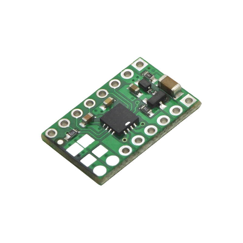
The DRV8833 is TI's dual H-bridge for low-voltage motors: it runs from 2.7 V to 10.8 V and each bridge takes two inputs, IN1 and IN2, that set forward, reverse, coast or brake (TI DRV8833 datasheet SLVSAR1E, pp. 5, 9). The Pololu carrier delivers 1.2 A continuous and 2 A peak per channel, or 2.4 A with both bridges in parallel, and its inputs accept 3 V and 5 V logic (Pololu #2130 product page). It is the usual upgrade from an L298N for battery robots, since its MOSFET outputs waste far less voltage.
The DRV8833 holds two full H-bridges built from N-channel MOSFETs. Each bridge has two inputs: drive one high and the other low and the motor turns; both low lets it coast, both high brakes it (TI datasheet, p. 9). PWM on one input sets speed, and the chip decides between fast and slow decay depending on which input you hold steady.
Its supply range of 2.7 V to 10.8 V (datasheet, p. 5) fits one or two lithium cells, four AA cells or a 5 V USB supply, which is why it is the common choice for small robots with N20 or TT gear motors. The absolute maximum is 11.8 V, so a 12 V supply is out of range.
The Pololu carrier adds reverse-battery protection, pulls SLP high so the driver is awake by default, and ties the current-sense pins to ground, which leaves current limiting off until you fit sense resistors (Pololu #2130 product page). Cheaper red HW-627 boards carry the same chip with different pin names (IN1 to IN4, EEP for sleep, ULT for fault).
DRV8833 pinout
| Pin | Function | Type |
|---|---|---|
| VIN | VIN2.7 V to 10.8 V | power in |
| VMM | VMM | power out |
| GND | GND | power in |
| AIN1 | PWM | input |
| AIN2 | PWM | input |
| BIN1 | PWM | input |
| BIN2 | PWM | input |
| AOUT1 | Motor A | output |
| AOUT2 | Motor A | output |
| BOUT1 | Motor B | output |
| BOUT2 | Motor B | output |
| SLP | Sleep (active low) | input |
| FLT | Fault (active low) | open collector |
| AISEN | Current sense A | passive |
| BISEN | Current sense B | passive |
How to wire the DRV8833
Pin by pin, for the board you have.
| DRV8833 | Arduino Uno | Note |
|---|---|---|
| AIN1 | D5 | |
| AIN2 | D6 | |
| BIN1 | D9 | |
| BIN2 | D10 | |
| GND | GND | |
| VIN | Battery + (4 x AA, about 6 V) | |
| GND | Battery - | The same GND pin row: battery minus and Uno GND meet here. |
| AOUT1 | Motor A | |
| AOUT2 | Motor A | |
| BOUT1 | Motor B | |
| BOUT2 | Motor B | |
| SLP | not connected | Pulled high on the board. |
- Power the motors from their own battery, not the Uno's 5V pin: motor start-up currents reset the board.
- Keep VIN at 10.8 V or less. A 3S lithium pack (up to 12.6 V) or a 12 V adapter exceeds the 11.8 V absolute maximum.
| DRV8833 | ESP32 DevKit V1 | Note |
|---|---|---|
| AIN1 | GPIO25 (D25) | |
| AIN2 | GPIO26 (D26) | |
| BIN1 | GPIO32 (D32) | |
| BIN2 | GPIO33 (D33) | |
| GND | GND | |
| VIN | Battery + (4 x AA, about 6 V) | |
| GND | Battery - | Battery minus and ESP32 GND share the driver's GND. |
| AOUT1 | Motor A | |
| AOUT2 | Motor A | |
| BOUT1 | Motor B | |
| BOUT2 | Motor B | |
| SLP | not connected | Pulled high on the board. |
- The inputs read 3.3 V as high (2 V threshold), and nothing on the logic side reaches the motor voltage, so no level shifting is needed.
- Keep the motor battery separate from the ESP32's USB or VIN supply and share ground only.
| DRV8833 | Raspberry Pi Pico | Note |
|---|---|---|
| AIN1 | GP6 | |
| AIN2 | GP7 | |
| BIN1 | GP8 | |
| BIN2 | GP9 | |
| GND | GND | |
| VIN | Battery + (4 x AA, about 6 V) | |
| GND | Battery - | Battery minus and Pico GND share the driver's GND. |
| AOUT1 | Motor A | |
| AOUT2 | Motor A | |
| BOUT1 | Motor B | |
| BOUT2 | Motor B | |
| SLP | not connected | Pulled high on the board. |
- Never take motor power from VBUS or VSYS; give the motors their own battery and share ground with the Pico.
DRV8833 code
Every example here compiles for its board.
// DRV8833 on Arduino Uno: wiring and a free simulation at https://www.tinkered.ai/components/drv8833
// DRV8833 on an Arduino Uno: AIN1 D5, AIN2 D6, BIN1 D9, BIN2 D10
const int AIN1 = 5, AIN2 = 6, BIN1 = 9, BIN2 = 10;

// speed from -255 (full reverse) to 255 (full forward), 0 = coast
void setMotor(int in1, int in2, int speed) {
  speed = constrain(speed, -255, 255);
  if (speed > 0) {        // forward, PWM on IN1 with IN2 low (fast decay)
    analogWrite(in1, speed);
    digitalWrite(in2, LOW);
  } else if (speed < 0) { // reverse, PWM on IN2 with IN1 low
    digitalWrite(in1, LOW);
    analogWrite(in2, -speed);
  } else {                // both low: coast
    digitalWrite(in1, LOW);
    digitalWrite(in2, LOW);
  }
}

void setup() {
  Serial.begin(115200);
  pinMode(AIN1, OUTPUT); pinMode(AIN2, OUTPUT);
  pinMode(BIN1, OUTPUT); pinMode(BIN2, OUTPUT);
  Serial.println("DRV8833 ready");
}

void loop() {
  for (int s = 0; s <= 255; s += 51) {
    setMotor(AIN1, AIN2, s);
    setMotor(BIN1, BIN2, -s);
    Serial.print("Motor A "); Serial.print(s);
    Serial.print(", motor B "); Serial.println(-s);
    delay(1000);
  }
  setMotor(AIN1, AIN2, 0);
  setMotor(BIN1, BIN2, 0);
  Serial.println("Coast");
  delay(2000);
}
// DRV8833 on ESP32 DevKit V1: wiring and a free simulation at https://www.tinkered.ai/components/drv8833
// DRV8833 on an ESP32 DevKit V1: AIN1 GPIO25, AIN2 GPIO26, BIN1 GPIO32, BIN2 GPIO33
const int AIN1 = 25, AIN2 = 26, BIN1 = 32, BIN2 = 33;

// speed from -255 (full reverse) to 255 (full forward), 0 = coast
void setMotor(int in1, int in2, int speed) {
  speed = constrain(speed, -255, 255);
  if (speed > 0) {        // forward, PWM on IN1 with IN2 low (fast decay)
    analogWrite(in1, speed);
    analogWrite(in2, 0);
  } else if (speed < 0) { // reverse, PWM on IN2 with IN1 low
    analogWrite(in1, 0);
    analogWrite(in2, -speed);
  } else {                // both low: coast
    analogWrite(in1, 0);
    analogWrite(in2, 0);
  }
}

void setup() {
  Serial.begin(115200);
  pinMode(AIN1, OUTPUT); pinMode(AIN2, OUTPUT);
  pinMode(BIN1, OUTPUT); pinMode(BIN2, OUTPUT);
  Serial.println("DRV8833 ready");
}

void loop() {
  for (int s = 0; s <= 255; s += 51) {
    setMotor(AIN1, AIN2, s);
    setMotor(BIN1, BIN2, -s);
    Serial.printf("Motor A %d, motor B %d\n", s, -s);
    delay(1000);
  }
  setMotor(AIN1, AIN2, 0);
  setMotor(BIN1, BIN2, 0);
  Serial.println("Coast");
  delay(2000);
}
// DRV8833 on Raspberry Pi Pico: wiring and a free simulation at https://www.tinkered.ai/components/drv8833
// DRV8833 on a Raspberry Pi Pico (arduino-pico): AIN1 GP6, AIN2 GP7, BIN1 GP8, BIN2 GP9
const int AIN1 = 6, AIN2 = 7, BIN1 = 8, BIN2 = 9;

// speed from -255 (full reverse) to 255 (full forward), 0 = coast
void setMotor(int in1, int in2, int speed) {
  speed = constrain(speed, -255, 255);
  if (speed > 0) {        // forward, PWM on IN1 with IN2 low (fast decay)
    analogWrite(in1, speed);
    analogWrite(in2, 0);
  } else if (speed < 0) { // reverse, PWM on IN2 with IN1 low
    analogWrite(in1, 0);
    analogWrite(in2, -speed);
  } else {                // both low: coast
    analogWrite(in1, 0);
    analogWrite(in2, 0);
  }
}

void setup() {
  Serial.begin(115200);
  analogWriteRange(255); // 0..255 duty, the arduino-pico default made explicit
  pinMode(AIN1, OUTPUT); pinMode(AIN2, OUTPUT);
  pinMode(BIN1, OUTPUT); pinMode(BIN2, OUTPUT);
  Serial.println("DRV8833 ready");
}

void loop() {
  for (int s = 0; s <= 255; s += 51) {
    setMotor(AIN1, AIN2, s);
    setMotor(BIN1, BIN2, -s);
    Serial.print("Motor A "); Serial.print(s);
    Serial.print(", motor B "); Serial.println(-s);
    delay(1000);
  }
  setMotor(AIN1, AIN2, 0);
  setMotor(BIN1, BIN2, 0);
  Serial.println("Coast");
  delay(2000);
}
Before you wire it
- Keep VIN between 2.7 V and 10.8 V (TI datasheet, p. 5); two lithium cells or four AA cells are the usual supplies.
- Join the motor supply's ground to your board's GND, or the inputs have no reference.
- Use two PWM-capable pins per motor if you want both directions at variable speed.
- Stay within 1.2 A continuous per channel on the Pololu carrier, or parallel the two bridges for 2.4 A on one motor (Pololu #2130).
- Never run it from 12 V: the absolute maximum is 11.8 V (datasheet, p. 5).
- Never set both inputs high and expect the motor to free-wheel: 1/1 is brake, 0/0 is coast (datasheet, p. 9).
- Never power the motors from a board's 5V or 3.3V pin; stall currents of an amp or more collapse the board's supply.
- Never expect current limiting out of the box: the carrier's ISEN pins are grounded until you add sense resistors (Pololu #2130).
- Each bridge follows the same truth table: IN1 high and IN2 low drives OUT1 high (forward), the reverse drives backward, both low coasts and both high brakes (TI datasheet, p. 9).
- For PWM, holding one input low while pulsing the other gives fast decay; holding one input high while pulsing the other gives slow decay, which keeps speed more linear with duty cycle (datasheet, p. 9).
- The IN pins have 150 kOhm pull-downs (datasheet, p. 6), so a motor stays still while your board boots with its pins floating.
- nSLEEP needs 2.5 V to wake (datasheet, p. 6); the carrier pulls it high, and a 3.3 V GPIO can drive it if you want to cut standby current.
- Add a 0.1 µF ceramic capacitor across each brushed motor's terminals to cut the electrical noise that can reset a nearby microcontroller.
Specifications
- Motor supply (VM)
- 2.7 V to 10.8 VTI DRV8833 datasheet SLVSAR1E, p. 5
- Absolute maximum VM
- 11.8 VTI DRV8833 datasheet SLVSAR1E, p. 5
- Current per channel (carrier)
- 1.2 A continuous, 2 A peak for a few seconds; 2.4 A continuous with the two bridges in parallelPololu DRV8833 carrier #2130 product page
- Chip current rating
- 1.5 A RMS, 2 A peak per H-bridge (HTSSOP PWP package)TI DRV8833 datasheet SLVSAR1E, p. 1
- Logic input high
- 2 V minimum (IN pins); 2.5 V minimum on nSLEEPTI DRV8833 datasheet SLVSAR1E, p. 6
- Input pull-downs
- 150 kOhm on the IN pins, 500 kOhm on nSLEEPTI DRV8833 datasheet SLVSAR1E, p. 6
- Bridge control
- IN1/IN2: 0/0 coast, 0/1 reverse, 1/0 forward, 1/1 brakeTI DRV8833 datasheet SLVSAR1E, p. 9
- Overcurrent trip
- 2 A minimum, 3.3 A typicalTI DRV8833 datasheet SLVSAR1E, p. 6
- Board protection
- Reverse-voltage protection FET on VIN; SLP pulled high; current limiting off (ISEN pins grounded)Pololu DRV8833 carrier #2130 product page
From the DRV8833 Dual H-Bridge Motor Driver, SLVSAR1E (revised July 2015), published by Texas Instruments.
Common mistakes
Running it from a 12 V adapter
The DRV8833 is a low-voltage part: 10.8 V operating and 11.8 V absolute maximum (datasheet, p. 5). Use the TB6612FNG or an L298N-class driver for 12 V motors.
Confusing coast and brake
Both inputs high shorts the motor through the low-side switches and stops it hard; both low lets it spin down (datasheet, p. 9). Code that writes HIGH to both to 'stop' gives a jerky halt.
Using the HW-627 board's labels with a Pololu tutorial
The cheap red boards name the pins IN1 to IN4, EEP (sleep) and ULT (fault). EEP on some of them must be pulled high before the driver wakes; check yours if the motors never move.
Expecting 1.5 A continuous per motor
The chip's 1.5 A RMS needs a good thermal pad layout (datasheet, p. 1). The small carrier is rated 1.2 A continuous (Pololu #2130); above that it trips its overcurrent or thermal shutdown.
DRV8833 questions
DRV8833 vs L298N: which is better?
For motors under about 10 V, the DRV8833. Its MOSFET bridges lose little voltage, while the L298N's bipolar outputs drop a couple of volts, so a 6 V battery delivers more to the motors through the DRV8833. The L298N wins only on supply voltage, since the DRV8833 stops at 10.8 V (TI datasheet, p. 5).
Can the DRV8833 drive a stepper motor?
Yes, a small bipolar stepper: one coil on each bridge, stepped in sequence from four GPIOs (the Arduino Stepper library works). It suits motors under about 1.2 A per coil at up to 10.8 V; for NEMA 17 motors on 12 V or more use a STEP/DIR driver such as the DRV8825.
Does the DRV8833 work with 3.3 V logic?
Yes. The IN pins read high from 2 V and nSLEEP from 2.5 V (datasheet, p. 6), and Pololu lists the inputs as 3 V and 5 V compatible. An ESP32 or Pico drives it directly.
What does the FLT pin do?
It is an open-drain output that goes low on overcurrent, overheating or undervoltage (Pololu #2130). Connect it to an input with the internal pull-up enabled if you want to detect a stalled motor.
Why do my motors only run in one direction?
Usually one input of the pair is not on a PWM pin, or the code writes PWM to the wrong pin for reverse. Each motor needs IN1 and IN2 both under control, and for reverse you pulse IN2 while holding IN1 low.
Build something with the DRV8833
- Build this
Two-wheel robot
Drive a small robot with two gear motors and steer by speed difference.
- Build this
Line follower
Follow a black line with IR sensors and two motors.
- Build this
Motorized blinds
Raise and lower a small blind with a geared motor and limit switches.
This page as plain Markdown, for ChatGPT, Claude or your own agent. /components/drv8833.md