DRV8825
A TI DRV8825 carrier board that drives one bipolar stepper motor from STEP and DIR pulses, at 8.2 V to 45 V and up to 1/32 microstepping.
- Motor supply (VMOT)8.2 V to 45 V
- Absolute maximum VMOT47 V
- Current per coil (carrier)About 1.5 A without heat sink or airflow, up to 2.2 A with extra cooling
- Chip current rating2.5 A per bridge at 24 V and 25 °C with proper heat sinking
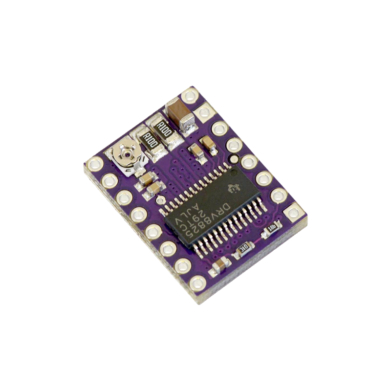
The DRV8825 is TI's bipolar stepper driver: one STEP pulse moves the motor one (micro)step, DIR sets the direction, and it runs motors from 8.2 V to 45 V (TI DRV8825 datasheet SLVSA73F, p. 1). The Pololu-style carrier handles about 1.5 A per coil without a heat sink, and you set that limit with the trimmer: current limit = VREF x 2 (Pololu #2133 product page). RST and SLP must be pulled high, and a 47 µF or larger capacitor goes across VMOT and GND.
The DRV8825 carrier is the pin-compatible, higher-voltage upgrade to the A4988 found in 3D printers and CNC shields. The chip takes the motor supply on VMOT, from 8.2 V to 45 V (TI datasheet, p. 1), makes its own logic supply internally, and turns STEP and DIR pulses into regulated coil currents. There is no logic VDD pin: the board talks to 3.3 V and 5 V controllers alike, since its inputs read high from 2.2 V (p. 6).
Three MODE pins pick full, half, 1/4, 1/8, 1/16 or 1/32 steps, and all three have pull-downs, so a board with them unconnected runs in full step (Pololu #2133 product page). The current limit is set with the trimmer by measuring VREF: Pololu's 0.100 ohm sense resistors make current limit = VREF x 2. The chip itself is rated for 2.5 A per bridge at 24 V with good heat sinking (datasheet, p. 1); on the small carrier, plan on about 1.5 A per coil without extra cooling.
RST and SLP both have pull-downs inside the chip (100 kOhm and 1 MOhm, datasheet p. 17), so the driver stays disabled until you pull them high. The usual trick is to join RST and SLP and tie them to your board's logic supply. EN is active low and enabled by default, which makes it a handy way to cut holding current from code.
DRV8825 pinout
| Pin | Function | Type |
|---|---|---|
| EN | Enable (active low) | input |
| M0 | Microstep select | input |
| M1 | Microstep select | input |
| M2 | Microstep select | input |
| RST | Reset (active low)2.2 V to 5.25 V for high | input |
| SLP | Sleep (active low)2.2 V to 5.25 V for high | input |
| STEP | STEP | input |
| DIR | Direction | input |
| VMOT | VMOT8.2 V to 45 V | power in |
| GND_MOT | GND | power in |
| B2 | Coil B | output |
| B1 | Coil B | output |
| A1 | Coil A | output |
| A2 | Coil A | output |
| FLT | Fault (active low) | open collector |
| GND_LOGIC | GND | power in |
How to wire the DRV8825
Pin by pin, for the board you have.
| DRV8825 | Arduino Uno | Note |
|---|---|---|
| STEP | D3 | |
| DIR | D2 | |
| EN | D8 | |
| RST | 5V | Join RST and SLP and take both to 5V. |
| SLP | 5V | |
| GND_LOGIC | GND | |
| M0 | not connected | M0, M1, M2 left open: full step (200 steps per turn on a 1.8° motor). |
| VMOT | Motor supply + (12 V) | 47 µF or larger electrolytic across VMOT and GND at the driver. |
| GND_MOT | Motor supply - and Uno GND | |
| A1 | Motor coil A | |
| A2 | Motor coil A | |
| B1 | Motor coil B | |
| B2 | Motor coil B |
- The motor runs from its own 8.2 V to 45 V supply, never from the Uno's 5V pin. Join the supply's ground to the Uno's GND.
- Set the current limit with the trimmer before the first run: VREF = current limit / 2, for example 0.75 V for 1.5 A.
- Never connect or disconnect the motor while VMOT is powered.
| DRV8825 | ESP32 DevKit V1 | Note |
|---|---|---|
| STEP | GPIO25 (D25) | |
| DIR | GPIO26 (D26) | |
| EN | GPIO27 (D27) | |
| RST | 3V3 | Join RST and SLP and take both to 3V3; 3.3 V is above the 2.2 V high threshold. |
| SLP | 3V3 | |
| GND_LOGIC | GND | |
| M0 | not connected | M0, M1, M2 left open: full step. |
| VMOT | Motor supply + (12 V) | 47 µF or larger electrolytic across VMOT and GND at the driver. |
| GND_MOT | Motor supply - and ESP32 GND | |
| A1 | Motor coil A | |
| A2 | Motor coil A | |
| B1 | Motor coil B | |
| B2 | Motor coil B |
- The driver's inputs take 3.3 V logic directly; nothing on the logic header reaches the motor voltage.
- Keep the motor supply separate from the ESP32's VIN and share only ground.
- Set VREF before connecting the motor, and never unplug the motor while VMOT is powered.
| DRV8825 | Raspberry Pi Pico | Note |
|---|---|---|
| STEP | GP2 | |
| DIR | GP3 | |
| EN | GP4 | |
| RST | 3V3(OUT) | Join RST and SLP and take both to 3V3(OUT). |
| SLP | 3V3(OUT) | |
| GND_LOGIC | GND | |
| M0 | not connected | M0, M1, M2 left open: full step. |
| VMOT | Motor supply + (12 V) | 47 µF or larger electrolytic across VMOT and GND at the driver. |
| GND_MOT | Motor supply - and Pico GND | |
| A1 | Motor coil A | |
| A2 | Motor coil A | |
| B1 | Motor coil B | |
| B2 | Motor coil B |
- Power the motor from its own supply, never from VBUS or VSYS, and share ground with the Pico.
- Set VREF before connecting the motor, and never unplug the motor while VMOT is powered.
DRV8825 code
Every example here compiles for its board.
// DRV8825 on Arduino Uno: wiring and a free simulation at https://www.tinkered.ai/components/drv8825
// DRV8825 on an Arduino Uno: STEP D3, DIR D2, EN D8, RST+SLP to 5V, full step
#include <AccelStepper.h>

const int STEP_PIN = 3;
const int DIR_PIN = 2;
const int EN_PIN = 8;
const long STEPS_PER_REV = 200; // 1.8 degree motor in full step

AccelStepper stepper(AccelStepper::DRIVER, STEP_PIN, DIR_PIN);

void setup() {
  Serial.begin(115200);
  pinMode(EN_PIN, OUTPUT);
  digitalWrite(EN_PIN, LOW); // EN is active low: LOW enables the outputs
  stepper.setMinPulseWidth(2); // DRV8825 needs at least 1.9 us high and low
  stepper.setMaxSpeed(400);    // steps per second
  stepper.setAcceleration(800);
  stepper.moveTo(STEPS_PER_REV);
  Serial.println("DRV8825 ready");
}

void loop() {
  if (stepper.distanceToGo() == 0) {
    Serial.print("Reached step ");
    Serial.println(stepper.currentPosition());
    delay(500);
    stepper.moveTo(-stepper.currentPosition()); // go back the other way
  }
  stepper.run();
}
// DRV8825 on ESP32 DevKit V1: wiring and a free simulation at https://www.tinkered.ai/components/drv8825
// DRV8825 on an ESP32 DevKit V1: STEP GPIO25, DIR GPIO26, EN GPIO27, RST+SLP to 3V3, full step
#include <AccelStepper.h>

const int STEP_PIN = 25;
const int DIR_PIN = 26;
const int EN_PIN = 27;
const long STEPS_PER_REV = 200; // 1.8 degree motor in full step

AccelStepper stepper(AccelStepper::DRIVER, STEP_PIN, DIR_PIN);

void setup() {
  Serial.begin(115200);
  pinMode(EN_PIN, OUTPUT);
  digitalWrite(EN_PIN, LOW); // EN is active low: LOW enables the outputs
  stepper.setMinPulseWidth(2); // DRV8825 needs at least 1.9 us high and low
  stepper.setMaxSpeed(400);
  stepper.setAcceleration(800);
  stepper.moveTo(STEPS_PER_REV);
  Serial.println("DRV8825 ready");
}

void loop() {
  if (stepper.distanceToGo() == 0) {
    Serial.print("Reached step ");
    Serial.println(stepper.currentPosition());
    delay(500);
    stepper.moveTo(-stepper.currentPosition());
  }
  stepper.run();
}
// DRV8825 on Raspberry Pi Pico: wiring and a free simulation at https://www.tinkered.ai/components/drv8825
// DRV8825 on a Raspberry Pi Pico (arduino-pico): STEP GP2, DIR GP3, EN GP4, RST+SLP to 3V3(OUT), full step
#include <AccelStepper.h>

const int STEP_PIN = 2;
const int DIR_PIN = 3;
const int EN_PIN = 4;
const long STEPS_PER_REV = 200; // 1.8 degree motor in full step

AccelStepper stepper(AccelStepper::DRIVER, STEP_PIN, DIR_PIN);

void setup() {
  Serial.begin(115200);
  pinMode(EN_PIN, OUTPUT);
  digitalWrite(EN_PIN, LOW); // EN is active low: LOW enables the outputs
  stepper.setMinPulseWidth(2); // DRV8825 needs at least 1.9 us high and low
  stepper.setMaxSpeed(400);
  stepper.setAcceleration(800);
  stepper.moveTo(STEPS_PER_REV);
  Serial.println("DRV8825 ready");
}

void loop() {
  if (stepper.distanceToGo() == 0) {
    Serial.print("Reached step ");
    Serial.println(stepper.currentPosition());
    delay(500);
    stepper.moveTo(-stepper.currentPosition());
  }
  stepper.run();
}
Before you wire it
- Pull RST and SLP high (tie them together to your logic supply): both have pull-downs inside the chip, so the driver stays off otherwise (TI datasheet, p. 17).
- Set the current limit before the first run: current limit = VREF x 2 on the Pololu carrier, so 0.75 V gives 1.5 A per coil.
- Put a 47 µF or larger electrolytic capacitor across VMOT and GND, close to the driver, to absorb the voltage spikes the ceramic capacitors alone allow (Pololu #2133 page).
- Keep STEP pulses at least 1.9 µs high and 1.9 µs low (datasheet, p. 7); with AccelStepper, call setMinPulseWidth(2).
- Wait 1.7 ms after SLP goes high before sending steps (datasheet, p. 7).
- Never connect or disconnect the motor while VMOT is powered: the inductive spike can destroy the driver.
- Never feed VMOT from a board's 5V pin: the driver needs at least 8.2 V and the motor current would brown out the board.
- Never run above about 1.5 A per coil without a heat sink or airflow; the chip's thermal shutdown starts at 150 °C (datasheet, p. 6).
- Never exceed 45 V on VMOT, and leave headroom for supply spikes: the absolute maximum is 47 V (datasheet, p. 4).
- The DRV8825 generates its own logic supply, so the carrier has no VDD pin. Logic inputs accept 2.2 V to 5.25 V as high (TI datasheet, p. 6), which suits 3.3 V and 5 V boards alike.
- MODE0 to MODE2 have pull-downs, so leaving them unconnected gives full step. M0 high gives half step, M1 high 1/4, M0 and M1 high 1/8, M2 high 1/16, and M2 with M0 or M1 high 1/32 (Pololu #2133 page).
- Measure VREF between the trimmer's metal top (or the board's ref test point) and GND with VMOT and logic powered. The 0.100 ohm sense resistors give current limit = VREF x 2.
- FLT is driven low on a fault. On the Pololu carrier it connects to SLP through a 10 kOhm resistor, so any external pull-up on SLP must be 4.7 kOhm or less (Pololu #2133 page).
- The overcurrent trip is 3 A typical (datasheet, p. 6); a shorted or miswired coil shuts the outputs off until RST is pulsed or power is cycled.
Specifications
- Motor supply (VMOT)
- 8.2 V to 45 VTI DRV8825 datasheet SLVSA73F, p. 1 and p. 4 (recommended operating conditions)
- Absolute maximum VMOT
- 47 VTI DRV8825 datasheet SLVSA73F, p. 4
- Current per coil (carrier)
- About 1.5 A without heat sink or airflow, up to 2.2 A with extra coolingPololu DRV8825 carrier #2133 product page
- Chip current rating
- 2.5 A per bridge at 24 V and 25 °C with proper heat sinkingTI DRV8825 datasheet SLVSA73F, p. 1
- Current limit setting
- Current limit = VREF x 2 (0.100 ohm sense resistors)Pololu DRV8825 carrier #2133 product page
- Logic input high
- 2.2 V to 5.25 V; low below 0.7 VTI DRV8825 datasheet SLVSA73F, p. 6
- STEP timing
- High and low each at least 1.9 µs; up to 250 kHzTI DRV8825 datasheet SLVSA73F, p. 7
- Microstepping
- Full, 1/2, 1/4, 1/8, 1/16, 1/32 via MODE0 to MODE2 (pulled down: full step)Pololu DRV8825 carrier #2133 product page
- Wake-up time
- 1.7 ms from SLP high until STEP is acceptedTI DRV8825 datasheet SLVSA73F, p. 7
- Protection
- Overcurrent trip at 3 A (typ), thermal shutdown from 150 °C, undervoltage lockout at 7.8 V (typ)TI DRV8825 datasheet SLVSA73F, p. 6
From the DRV8825 Stepper Motor Controller IC, SLVSA73F (revised July 2014), published by Texas Instruments.
Common mistakes
Leaving RST and SLP floating
On the A4988 a missing RST link already causes trouble; on the DRV8825 both RST and SLP have pull-downs (TI datasheet, p. 17), so the motor never moves. Join them and tie them to the board's 3.3 V or 5 V.
Copying the A4988's VREF formula
The A4988 carrier uses a different sense resistor and formula. On the DRV8825 carrier the limit is VREF x 2 (Pololu #2133), so an A4988 setting can leave the motor at the wrong current. Re-measure after swapping drivers.
Too-short STEP pulses
The DRV8825 needs 1.9 µs high and low (datasheet, p. 7), nearly twice the A4988's minimum. Fast hand-written step loops or libraries set for 1 µs miss steps; set AccelStepper's minimum pulse width to 2 µs.
Skipping the bulk capacitor
Long supply leads and the board's ceramic capacitors can ring well above the supply voltage when the motor switches. Pololu asks for at least 47 µF across VMOT and GND; without it a 24 V supply can kill the chip on power-up.
Expecting 2.5 A from the bare carrier
The 2.5 A figure is the chip's rating with proper heat sinking (datasheet, p. 1). The small carrier manages about 1.5 A per coil in free air; above that it heats up and shuts down until it cools.
DRV8825 questions
DRV8825 or A4988: which should I use?
The DRV8825 runs up to 45 V against the A4988's 35 V, adds 1/32 microstepping and handles about 1.5 A per coil on the bare carrier (Pololu #2133). The two are pin compatible, but the DRV8825 needs longer STEP pulses (1.9 µs) and uses a different VREF formula, so recheck both when you swap.
How do I set the DRV8825 current limit?
Power the logic and VMOT, leave the motor disconnected or idle, and measure VREF from the trimmer to GND. On the Pololu carrier current limit = VREF x 2, so for a 1 A motor turn the trimmer to 0.5 V (Pololu #2133 product page).
Does the DRV8825 work with an ESP32 or a 3.3 V board?
Yes. Its logic inputs read high from 2.2 V (TI datasheet, p. 6), so 3.3 V GPIOs drive STEP, DIR and EN directly. Tie RST and SLP to 3.3 V rather than 5 V, and keep the motor on its own supply.
Why does my DRV8825 get hot and the motor stutter?
Usually the current limit is set above what the carrier can shed, or the motor stalls. Above about 1.5 A per coil it needs a heat sink or a fan (Pololu #2133), and at 150 °C the chip's thermal shutdown cuts the outputs (datasheet, p. 6). Lower VREF or add cooling.
What voltage should I use for VMOT?
Anything from 8.2 V to 45 V (datasheet, p. 1). Higher voltage lets the current rise faster in the coils, which keeps torque at speed, so 12 V or 24 V supplies are common. Add the 47 µF capacitor and never hot-plug the motor.
Build something with the DRV8825
- Build this
Camera slider
Move a camera along a rail at a slow, steady speed with microstepping.
- Build this
Automatic fish feeder
Turn a feed wheel a set angle twice a day.
- Build this
Turntable for 3D scanning
Rotate an object in precise increments for photos.
This page as plain Markdown, for ChatGPT, Claude or your own agent. /components/drv8825.md