CD4051 8-Channel Analog Mux
The CD4051 is an 8-channel analog multiplexer that lets one analog pin read eight sensors, or one output reach eight loads.
- FunctionSingle 8-channel analog multiplexer/demultiplexer, bidirectional
- Supply3 V to 20 V single; ±3 V to ±10 V dual
- On-resistance470 Ω typ, 1050 Ω max at VDD 5 V; 180 Ω typ at 10 V; 125 Ω typ at 15 V (25 °C)
- Select input high3.5 V min at VDD 5 V; 7 V at 10 V
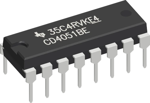
The CD4051B is an 8-channel analog multiplexer: three select pins A, B and C connect one of channels 0 to 7 to the common pin COM, in both directions (TI CD4051B datasheet SCHS047O, pp. 1, 17). Power VDD (pin 16) from the board's logic supply (it runs from 3 V to 20 V, p. 1), tie VSS (pin 8), VEE (pin 7) and INH (pin 6) to GND, wire A, B, C (pins 11, 10, 9) to three outputs and COM (pin 3) to an analog input. The closed switch is about 470 Ω at 5 V (1050 Ω max, p. 6), fine for an ADC but not for driving loads.
The CD4051B is a single 8-channel analog multiplexer and demultiplexer: a set of CMOS analog switches with a 3-bit address decoder. The binary value on select inputs A, B and C (A the lowest bit) chooses which of channels 0 to 7 connects to the common pin COM, and the inhibit pin INH turns every channel off when high (TI CD4051B datasheet SCHS047O, pp. 14, 17). The switches pass signals both ways, so the same chip reads eight analog sources into one ADC pin, or routes one output to eight destinations.
It runs from 3 V to 20 V on a single supply, or ±3 V to ±10 V on a split supply (datasheet, p. 1). VDD is the positive supply, VSS the logic ground and VEE the lowest signal voltage: tie VEE to VSS for a single supply, and keep every channel and COM between VEE and VDD, since inputs cannot be pushed more than 0.5 V beyond the rails (p. 19). Built-in level conversion lets the logic swing between VSS and VDD while the analog signal swings down to VEE (p. 1).
A closed channel is not a wire. Its on-resistance is 470 Ω typical and 1050 Ω maximum at VDD 5 V, falling to 180 Ω at 10 V and 125 Ω at 15 V (datasheet, p. 6), and TI notes the chip cannot source or sink current: whatever flows only passes through it (p. 19). That makes it ideal for potentiometers, sensors, buttons and small LEDs read or driven through their own resistors, and wrong for motors or relays. Channel switching is break-before-make (p. 16), and the address-to-output delay is 450 ns typical at 5 V (p. 8).
CD4051 8-Channel Analog Mux pinout
| Pin | Function | Type |
|---|---|---|
| CH4 | ADC channel 4: switched to COM when selected | free |
| CH6 | ADC channel 6: switched to COM when selected | free |
| COM | ADC common: the selected channel's signal | free |
| CH7 | ADC channel 7: switched to COM when selected | free |
| CH5 | ADC channel 5: switched to COM when selected | free |
| INH | Digital | input |
| VEE | 7 VEE (negative supply: tie to VSS for a single supply)3–5 V | power in |
| VSS | 8 VSS (ground) | power in |
| VDD | 16 VDD (3-20 V over VSS)3–5 V | power in |
| CH2 | ADC channel 2: switched to COM when selected | free |
| CH1 | ADC channel 1: switched to COM when selected | free |
| CH0 | ADC channel 0: switched to COM when selected | free |
| CH3 | ADC channel 3: switched to COM when selected | free |
| A | Digital | input |
| B | Digital | input |
| C | Digital | input |
How to wire the CD4051 8-Channel Analog Mux
Pin by pin, for the board you have.
| CD4051 8-Channel Analog Mux | Arduino Uno | Note |
|---|---|---|
| VDD | 5V | |
| VSS | GND | |
| VEE | GND | |
| INH | GND | |
| A | D2 | |
| B | D3 | |
| C | D4 | |
| COM | A0 |
| CD4051 8-Channel Analog Mux | ESP32 DevKit V1 | Note |
|---|---|---|
| VDD | 3V3 | |
| VSS | GND | |
| VEE | GND | |
| INH | GND | |
| A | GPIO13 (D13) | |
| B | GPIO14 (D14) | |
| C | GPIO27 (D27) | |
| COM | GPIO33 (D33) |
| CD4051 8-Channel Analog Mux | Raspberry Pi Pico | Note |
|---|---|---|
| VDD | 3V3 | |
| VSS | GND | |
| VEE | GND | |
| INH | GND | |
| A | GP0 | |
| B | GP1 | |
| C | GP2 | |
| COM | GP28 |
CD4051 8-Channel Analog Mux code
Every example here compiles for its board.
// CD4051 8-Channel Analog Mux on Arduino Uno: wiring and a free simulation at https://www.tinkered.ai/components/cd4051-multiplexer
#include <Arduino.h>

const int SEL_A = 2;
const int SEL_B = 3;
const int SEL_C = 4;
const int MUX_COM = A0;

int readChannel(int ch) {
  digitalWrite(SEL_A, ch & 1);
  digitalWrite(SEL_B, (ch >> 1) & 1);
  digitalWrite(SEL_C, (ch >> 2) & 1);
  delayMicroseconds(10);   // the switch settles (about 0.5 µs at 5 V)
  return analogRead(MUX_COM);
}

void setup() {
  Serial.begin(115200);
  pinMode(SEL_A, OUTPUT);
  pinMode(SEL_B, OUTPUT);
  pinMode(SEL_C, OUTPUT);
}

void loop() {
  Serial.print("pot 1: ");
  Serial.print(readChannel(0));
  Serial.print("  pot 2: ");
  Serial.println(readChannel(1));
  delay(200);
}
Before you wire it
- VDD to the board's logic supply (5V on an Uno, 3V3 on an ESP32, a Pico, an STM32). VSS and VEE to GND.
- A, B, C to three GPIOs set as OUTPUT;
- INH to GND (or a GPIO, LOW to enable);
- COM to an analog pin (to read) or an output pin (to drive).
- Select, then read: digitalWrite(A, ch & 1); digitalWrite(B, (ch >> 1) & 1); digitalWrite(C, (ch >> 2) & 1);, then delayMicroseconds(10), then analogRead(COM).
- Every source on a channel runs from the CD4051's VDD (a potentiometer between VDD and GND), so no channel goes above VDD.
- Unused channels may stay open. An open channel reads a floating value: never act on it.
- No VEE left open: tie it to VSS (GND) for a single supply.
- No INH left open or tied HIGH: every channel stays off.
- No CD4051 on 5 V with a 3.3 V board's select pins: power it from 3V3.
- No signal above VDD or below VEE on a channel or COM: a 12 V source needs a divider.
- No motors or relays switched through it: it passes a few milliamps through up to 1050 Ω (470 Ω typical).
- Power VDD (pin 16) from the microcontroller board's logic supply: 5 V on an Uno, 3.3 V on an ESP32, Pico or STM32. At VDD 5 V the select inputs need 3.5 V for a high (TI datasheet, p. 8), more than a 3.3 V pin guarantees.
- Tie VSS (pin 8) and VEE (pin 7) to GND for a single supply. VEE sets the lowest voltage a channel may carry; left open, the switches have no defined negative rail.
- Tie INH (pin 6) to GND, or drive it from a GPIO and hold it low: INH high turns every channel off (TI datasheet, p. 17).
- Keep every channel and COM between VEE and VDD, no more than 0.5 V beyond (TI datasheet, p. 19). Power potentiometers and sensors on the channels from the same VDD, and divide down anything higher, such as a 12 V signal.
- After changing A, B and C, wait a few microseconds before reading: the address-to-signal delay is up to 720 ns at 5 V (TI datasheet, p. 8), and the ADC's sample capacitor needs time to settle through the switch's 470 Ω to 1050 Ω (p. 6).
- Place a 0.1 µF ceramic capacitor between VDD and VSS at the chip, as TI recommends (datasheet, p. 19).
- On-resistance is 1050 Ω at most at 5 V (470 Ω typical).
Specifications
- Function
- Single 8-channel analog multiplexer/demultiplexer, bidirectionalTI CD4051B datasheet SCHS047O, p. 1
- Supply
- 3 V to 20 V single; ±3 V to ±10 V dualTI CD4051B datasheet SCHS047O, p. 1
- On-resistance
- 470 Ω typ, 1050 Ω max at VDD 5 V; 180 Ω typ at 10 V; 125 Ω typ at 15 V (25 °C)TI CD4051B datasheet SCHS047O, p. 6
- Select input high
- 3.5 V min at VDD 5 V; 7 V at 10 VTI CD4051B datasheet SCHS047O, p. 8
- Switching delay
- Address to signal out: 450 ns typ, 720 ns max at VDD 5 VTI CD4051B datasheet SCHS047O, p. 8
- Channel selection
- Channel = A + 2B + 4C with INH low; INH high turns all channels offTI CD4051B datasheet SCHS047O, p. 17
- Current
- No drive of its own: current only passes through; ±10 mA absolute max into any one inputTI CD4051B datasheet SCHS047O, pp. 5, 19
- Signal range
- VEE to VDD; inputs no more than 0.5 V beyond VDD or VEETI CD4051B datasheet SCHS047O, p. 19
- Pinout (DIP-16)
- CH4 1, CH6 2, COM 3, CH7 4, CH5 5, INH 6, VEE 7, VSS 8, C 9, B 10, A 11, CH3 12, CH0 13, CH1 14, CH2 15, VDD 16TI CD4051B datasheet SCHS047O, p. 3
- Decoupling
- 0.1 µF on the supply pin, as close as possibleTI CD4051B datasheet SCHS047O, p. 19
- Supply voltage
- 3–20 Vmaker's datasheet, checked 29 Oct 2026
- Maximum supply voltage
- 20 V
- Dimensions
- 19.3 × 7.62 × 7.11 mm
- Weight
- 1 g
From the Texas Instruments's datasheet, published by Texas Instruments.
Common mistakes
Leaving VEE unconnected
VEE is the negative rail of the analog switches. On a single supply it must go to VSS (GND); left open, signals pass badly or not at all. TI's pinout lists it as the negative power input (datasheet, p. 3).
INH floating or high
INH high turns every channel off (TI datasheet, p. 17), so every read returns the same floating value. Tie it to GND, or drive it low from a GPIO.
5 V chip on a 3.3 V board
With VDD at 5 V the select pins need at least 3.5 V for a high (TI datasheet, p. 8), so a 3.3 V board's outputs can pick the wrong channel. Power the CD4051 from 3.3 V on a 3.3 V board.
Switching motors or relays through it
Each closed channel is 470 Ω typical and up to 1050 Ω at 5 V (TI datasheet, p. 6), and the chip has no drive of its own (p. 19). Use it for signals, and drive loads with transistors or a driver IC.
Reading too soon after switching
Reading the ADC the instant A, B and C change can catch the previous channel, because the address-to-signal delay reaches 720 ns at 5 V (TI datasheet, p. 8). Add a short delay, and read twice when the source impedance is high.
CD4051 8-Channel Analog Mux questions
How do I connect a CD4051 to an Arduino?
Wire VDD (pin 16) to 5 V, VSS (pin 8), VEE (pin 7) and INH (pin 6) to GND, A, B, C (pins 11, 10, 9) to three digital outputs, and COM (pin 3) to an analog input such as A0 (TI CD4051B datasheet, p. 3). Set the channel number on A, B, C (A is the lowest bit, p. 17), wait a few microseconds, then call analogRead().
Can I use a CD4051 with an ESP32 or Raspberry Pi Pico?
Yes, power it from 3.3 V: it runs from 3 V upward (TI datasheet, p. 1). Powered from 5 V it would need 3.5 V on the select pins (p. 8) and could pass up to 5 V into the board's ADC, which a 3.3 V pin cannot take.
Why do all eight channels read the same value?
Usually INH is high or floating, which turns every channel off (TI datasheet, p. 17), or A, B and C were never set as outputs. Also check that VEE is on GND and that you wait a few microseconds after changing the address (p. 8).
Can the CD4051 drive LEDs as a demultiplexer?
Yes, signals pass both ways (TI datasheet, p. 1): drive COM from an output and the selected channel follows it. The switch adds about 470 Ω at 5 V (p. 6) and the chip cannot source current itself (p. 19), so only one LED at a time is lit, dimly, through its own resistor.
CD4051 vs 74HC4051: which should I use?
Both share the industry-standard 4051 pinout (TI CD4051B datasheet, p. 1). The CD4051B runs up to 20 V and suits higher-voltage or split-supply signals. The CD74HC4051 switches 0 V to 10 V but has a much lower on-resistance, 70 Ω typical at 4.5 V across its supplies (TI CD74HC4051 datasheet SCHS122O, p. 1), against the CD4051B's 470 Ω at 5 V (p. 6). For 3.3 V or 5 V Arduino projects either works; the 74HC4051 settles faster into an ADC.
How many analog inputs can I add with CD4051s?
Each chip adds eight channels to one ADC pin. TI shows three chips addressed together for a 24-to-1 multiplexer, with the inhibit pins choosing the chip (datasheet, p. 14).
Build something with the CD4051 8-Channel Analog Mux
- Build this
Eight-knob MIDI or synth controller
Read eight potentiometers through one analog pin and send their positions as MIDI control changes.
- Build this
Multi-sensor plant monitor
Scan several soil moisture or light sensors on one ADC pin and log them in turn.
- Build this
Keypad or button scanner
Poll eight buttons through one input pin, the keypad application TI itself describes (datasheet, p. 18).
- Build this
Audio or signal selector
Route one of eight low-level signals to an amplifier or measurement input under microcontroller control.
This page as plain Markdown, for ChatGPT, Claude or your own agent. /components/cd4051-multiplexer.md