ATtiny85 Digispark
An 8-pin ATtiny85 microcontroller, sold bare or as the thumb-sized Digispark USB board with the micronucleus bootloader.
- MicrocontrollerATtiny85, 8-bit AVR; 16.5 MHz on the Digispark (internal PLL)
- Memory8 KB flash, 512 B SRAM, 512 B EEPROM; 6,012 bytes left for sketches after micronucleus
- Supply and speed2.7 V to 5.5 V; 20 MHz needs 4.5 V to 5.5 V, 10 MHz up to 2.7 V
- I/O6 pins (P0 to P5); P3 and P4 used by USB, P5 is RESET; PWM on P0, P1 and P4; ADC on P2 to P5
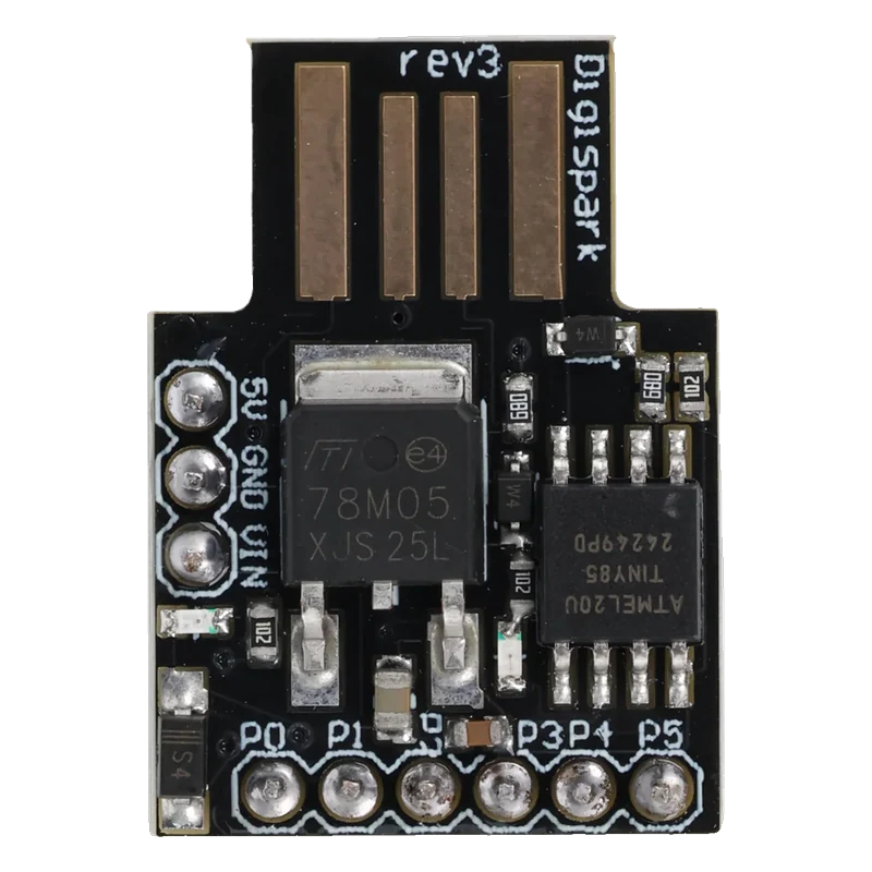
The ATtiny85 is an 8-pin AVR with 8 KB of flash, 512 bytes of SRAM, 512 bytes of EEPROM and 6 I/O pins (ATtiny85 datasheet, p. 1). On a Digispark board it runs at 16.5 MHz, plugs straight into a USB port and is programmed by the micronucleus bootloader, which leaves 6,012 bytes for your sketch (Digistump boards.txt). P3 and P4 are the USB data lines, so the board has 4 pins free while it talks USB and 6 otherwise (Digistump product page; usbconfig.h).
The ATtiny85 packs a full AVR core into an 8-pin package: 6 I/O lines, a 10-bit ADC with 4 single-ended inputs, two 8-bit timers and a USI block that does I2C or SPI in hardware assisted software (ATtiny85 datasheet, p. 1). It has no UART and only 512 bytes of SRAM, so it suits small, focused jobs: a sensor that switches something, a LED effect, a USB key that types a password.
The Digispark puts that chip on a board shaped like a USB plug, with a 5 V regulator for 7 V to 35 V input, a power LED and a user LED (Digistump product page). USB is bit-banged in firmware with V-USB on PB3 (D-) and PB4 (D+) (Digistump usbconfig.h), so the chip runs from its internal PLL at 16.5 MHz, a frequency USB timing needs (Digistump boards.txt).
Uploading is unlike an Arduino Uno: click Upload with the board unplugged, then plug it in when the IDE asks, within 60 seconds (Digistump platform.txt). The micronucleus bootloader runs at every reset and waits about 6 seconds for a host before starting your sketch (micronucleus t85_default config), which is why a Digispark pauses briefly each time it powers up.
ATtiny85 Digispark pinout
| Pin | Function | Type |
|---|---|---|
| 5V | 5V5 V | power out |
| GND | GND | power in |
| VIN | VIN7 V to 35 V (12 V or less recommended) | power in |
| P0 | PWM (OC0A), I2C SDA (USI), SPI MOSI/DI (USI), AREF, Digital5 V | bidirectional |
| P1 | PWM (OC0B/OC1A), SPI MISO/DO (USI), Digital5 V | bidirectional |
| P2 | ADC1 (A1), I2C SCL (USI), SPI SCK (USI), INT0, Digital5 V | bidirectional |
| P3 | ADC3 (A3), USB D-, Digital5 V | bidirectional |
| P4 | ADC2 (A2), PWM (OC1B), USB D+, Digital5 V | bidirectional |
| P5 | ADC0 (A0), RESET5 V | bidirectional |
ATtiny85 Digispark code
Every example here compiles for its board.
// ATtiny85 Digispark on ATtiny85 Digispark: wiring and a free simulation at https://www.tinkered.ai/components/attiny85
// ATtiny85: dim an LED with a potentiometer.
// LED + 330 ohm resistor on PB1 (P1 on a Digispark, where the on-board LED also sits).
// Potentiometer: ends to 5V and GND, wiper to PB2 (P2, ADC1).
// The ATtiny85 has no hardware UART, so this sketch reports through the LED alone.

#ifndef A1
#define A1 1                    // some ATtiny85 cores read analogRead() by channel number
#endif

const int LED_PIN = 1;          // PB1: Timer0 PWM (OC0B)
const int POT_PIN = A1;         // PB2: ADC channel 1

void setup() {
  pinMode(LED_PIN, OUTPUT);
  // Three quick blinks to show the sketch started
  for (int i = 0; i < 3; i++) {
    digitalWrite(LED_PIN, HIGH);
    delay(100);
    digitalWrite(LED_PIN, LOW);
    delay(100);
  }
}

void loop() {
  int raw = analogRead(POT_PIN);         // 10-bit: 0 to 1023 for 0 to VCC
  int brightness = raw / 4;              // 0 to 255 for analogWrite
  analogWrite(LED_PIN, brightness);
  delay(20);
}
Before you wire it
- Start the upload with the Digispark unplugged and plug it in when the IDE says so; the tool waits 60 seconds (Digistump platform.txt).
- Install the libusb driver on Windows (Zadig on Windows 10 and later) before the first upload (micronucleus README).
- Leave P3 and P4 free of loads and pull-downs when the sketch uses USB (Digistump keyboard or serial libraries).
- Keep each pin within 40 mA absolute maximum, and the whole chip within 200 mA (ATtiny85 datasheet, p. 161).
- Count bytes: 512 bytes of SRAM covers the stack and every variable, so keep strings in flash with F() or PROGMEM (ATtiny85 datasheet, p. 1).
- Never pull P5 low unless you want a reset, and never disable the reset pin without a high-voltage programmer to undo it.
- Never feed more than 5.5 V to the chip or the 5V pin; higher voltages go to VIN (ATtiny85 datasheet, p. 1; Digistump product page).
- Never expect Serial to work as on an Uno: the ATtiny85 has no hardware UART.
- A low-speed USB device carries a 1.5 kOhm pull-up on D-, here P3, so P3 reads high and loads anything wired to it (USB 2.0 specification, section 7.1.5).
- PWM is on P0 and P1 from Timer0 and on P4 from Timer1 (ATtiny85 datasheet, p. 2); P4's PWM shares the USB D+ line.
- I2C uses the USI on P0 (SDA) and P2 (SCL) and needs external pull-ups; most cores provide a Wire or TinyWire library for it.
- On boards with the LED on P1 (Model A), any signal on P1 also drives that LED (Digistump Start example).
- The bootloader starts at every reset, so a Digispark always waits a few seconds before running its sketch (micronucleus t85_default, AUTO_EXIT_MS 6000).
Specifications
- Microcontroller
- ATtiny85, 8-bit AVR; 16.5 MHz on the Digispark (internal PLL)Microchip ATtiny25/45/85 datasheet (Atmel-2586Q, 08/2013), p. 1; DigistumpArduino boards.txt, digispark-tiny entry
- Memory
- 8 KB flash, 512 B SRAM, 512 B EEPROM; 6,012 bytes left for sketches after micronucleusMicrochip ATtiny25/45/85 datasheet (Atmel-2586Q, 08/2013), p. 1; DigistumpArduino boards.txt, digispark-tiny entry
- Supply and speed
- 2.7 V to 5.5 V; 20 MHz needs 4.5 V to 5.5 V, 10 MHz up to 2.7 VMicrochip ATtiny25/45/85 datasheet (Atmel-2586Q, 08/2013), p. 1
- I/O
- 6 pins (P0 to P5); P3 and P4 used by USB, P5 is RESET; PWM on P0, P1 and P4; ADC on P2 to P5Digistump Digispark USB Development Board product page (digistump.com/products/1); Microchip ATtiny25/45/85 datasheet (Atmel-2586Q, 08/2013), p. 2
- Current per I/O pin
- 40 mA absolute maximum per pin, 200 mA through VCC and GNDMicrochip ATtiny25/45/85 datasheet (Atmel-2586Q, 08/2013), p. 161
- ADC
- 10-bit, 4 single-ended channelsMicrochip ATtiny25/45/85 datasheet (Atmel-2586Q, 08/2013), p. 1
- USB
- Software USB (V-USB) on PB3 (D-) and PB4 (D+); no USB-serial chipDigistumpArduino usbconfig.h (V-USB pin config for the ATtiny85)
- Board power
- USB 5 V or VIN 7 V to 35 V (12 V or less recommended) into a 500 mA 5 V regulatorDigistump Digispark USB Development Board product page (digistump.com/products/1)
- Bootloader
- micronucleus, about 1.5 KB; runs at every reset and times out after about 6 smicronucleus README and firmware/configuration/t85_default/bootloaderconfig.h
From the Microchip ATtiny25/45/85 datasheet (Atmel-2586Q), published by Microchip (ATtiny85); Digistump (Digispark).
Common mistakes
Plugging the board in before clicking Upload
The bootloader listens only for a few seconds after reset. Click Upload first, wait for the prompt, then plug the Digispark in (Digistump platform.txt, --timeout 60).
Running out of RAM
With 512 bytes of SRAM (ATtiny85 datasheet, p. 1), a few String objects or a buffer for 60 LEDs can crash the sketch with no error. Keep text in flash with F() and size arrays by hand.
Wiring a sensor to P3 or P4
P3 and P4 carry USB. A sensor there can stop the board from enumerating or uploading, and P3's pull-up skews analog readings (Digistump usbconfig.h). Use P0 to P2 first.
Windows shows Unknown Device
Micronucleus needs the libusb driver on Windows; install it with Zadig as the micronucleus README describes. macOS and Linux need no driver.
ATtiny85 Digispark questions
How do I upload code to a Digispark ATtiny85?
Install the Digistump board package, select Digispark (Default 16.5 MHz), click Upload with the board unplugged, and plug it in when prompted within 60 seconds (Digistump platform.txt). The micronucleus bootloader takes the sketch over USB and runs it.
How much memory does the ATtiny85 have?
8 KB of flash, 512 bytes of SRAM and 512 bytes of EEPROM (ATtiny85 datasheet, p. 1). On a Digispark the bootloader leaves 6,012 bytes of flash for sketches (Digistump boards.txt).
Why does my Digispark wait a few seconds before running?
Micronucleus starts at every reset and waits for an upload before jumping to your sketch, about 6 seconds in its default ATtiny85 configuration (micronucleus t85_default, AUTO_EXIT_MS 6000).
Does the ATtiny85 have Serial?
No hardware UART: the ATtiny85's serial-capable block is the USI, used for I2C and SPI (ATtiny85 datasheet, p. 1). On a Digispark, Digistump's DigiCDC library gives a USB serial port in software, or SoftwareSerial can drive a USB-serial adapter.
Which Digispark pins can I use?
All six, P0 to P5, but P3 and P4 are the USB lines and P5 is reset (Digistump product page; usbconfig.h). P0, P1 and P2 are the safest; PWM is on P0, P1 and P4 and analog input on P2 to P5.
ATtiny85 vs Arduino Nano: when is the ATtiny enough?
When the job needs at most 6 pins, a few KB of code and no serial port: a LED effect, a timer or a USB key. The Nano's ATmega328P has 32 KB of flash, 2 KB of SRAM and a hardware UART (ATmega328P datasheet, pp. 1, 2), which suits anything bigger.
Build something with the ATtiny85 Digispark
- Build this
USB password key
A Digispark that types a long passphrase when plugged in.
- Build this
Mood light
An ATtiny85 cycling colours on a short WS2812B strip.
- Build this
Night light switch
An LDR on the ADC turns an LED on in the dark.
This page as plain Markdown, for ChatGPT, Claude or your own agent. /components/attiny85.md