Arduino Pro Mini
A tiny ATmega328P board without USB, sold as 5 V/16 MHz and 3.3 V/8 MHz versions, programmed through an FTDI-style USB-serial adapter.
- MicrocontrollerATmega328P, 16 MHz on the 5 V version, 8 MHz on the 3.3 V version
- Why 8 MHz at 3.3 VThe chip is rated 0 to 10 MHz at 2.7 V to 5.5 V and 0 to 20 MHz only at 4.5 V to 5.5 V
- Memory32 KB flash (30,720 bytes for sketches), 2 KB SRAM, 1 KB EEPROM
- USBNone on board: a 5 V or 3.3 V USB-serial adapter on the 6-pin header
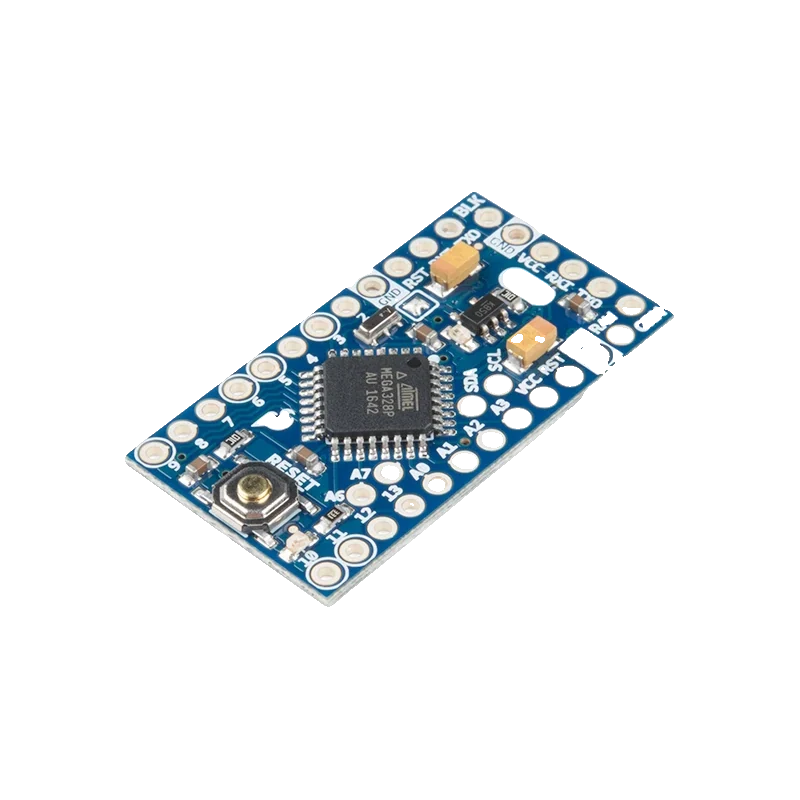
The Arduino Pro Mini is an 18 x 33 mm (0.7 x 1.3 in) ATmega328P board in two versions: 5 V at 16 MHz and 3.3 V at 8 MHz, with 32 KB of flash and 2 KB of SRAM (Arduino Pro Mini docs). It has no USB, so you upload through a USB-serial adapter on its 6-pin BLK-to-GRN header, choosing the 5 V or 3.3 V adapter to match (Arduino Pro Mini guide). Its regulator takes up to 12 V on RAW and supplies 150 mA (Arduino docs; SparkFun graphical datasheet).
The Pro Mini is the Uno's ATmega328P with everything that isn't needed in a finished project removed: no USB chip, no connector, no headers. SparkFun designed it for Arduino for installations where space matters (Arduino Pro Mini docs). Clones of the SparkFun layout are everywhere, so this pinout applies to most boards sold as Pro Mini.
Pick the version for your peripherals. The 5 V board runs at 16 MHz like an Uno; the 3.3 V board runs at 8 MHz because the ATmega328P is only rated to 10 MHz below 4.5 V (ATmega328P datasheet, p. 2), and its pins must only see 3.3 V signals. Selecting the wrong clock in the IDE makes every delay and baud rate off by two.
Programming goes through the 6-pin header on the short edge, labelled BLK, GND, VCC, RXI, TXO and GRN to match an FTDI cable's wire colours. The GRN pin reaches RESET through a 100 nF capacitor, so the adapter's DTR or RTS line resets the board for each upload (Arduino Pro Mini docs). A4/A5 (I2C) and the analog-only A6/A7 are inner holes, not on the edge rows (SparkFun tutorial).
Arduino Pro Mini pinout
| Pin | Function | Type |
|---|---|---|
| TXO | UART TX, Digital (D1)VCC: 5 V or 3.3 V by version | output |
| RXI | UART RX, Digital (D0)VCC: 5 V or 3.3 V by version | input |
| RST | Reset (active low)VCC: 5 V or 3.3 V by version | input |
| GND | GND | power in |
| D2 | INT0, DigitalVCC: 5 V or 3.3 V by version | bidirectional |
| D3 | PWM, INT1, DigitalVCC: 5 V or 3.3 V by version | bidirectional |
| D4 | DigitalVCC: 5 V or 3.3 V by version | bidirectional |
| D5 | PWM, DigitalVCC: 5 V or 3.3 V by version | bidirectional |
| D6 | PWM, DigitalVCC: 5 V or 3.3 V by version | bidirectional |
| D7 | DigitalVCC: 5 V or 3.3 V by version | bidirectional |
| D8 | DigitalVCC: 5 V or 3.3 V by version | bidirectional |
| D9 | PWM, DigitalVCC: 5 V or 3.3 V by version | bidirectional |
| RAW | RAW5 V version: 6 V to 12 V recommended; 3.3 V version: 4 V to 12 V | power in |
| GND-2 | GND | power in |
| RST-2 | Reset (active low)VCC: 5 V or 3.3 V by version | input |
| VCC | VCCRegulated 5 V or 3.3 V, matching the version | power in |
| A3 | ADC3, Digital (D17)VCC: 5 V or 3.3 V by version | bidirectional |
| A2 | ADC2, Digital (D16)VCC: 5 V or 3.3 V by version | bidirectional |
| A1 | ADC1, Digital (D15)VCC: 5 V or 3.3 V by version | bidirectional |
| A0 | ADC0, Digital (D14)VCC: 5 V or 3.3 V by version | bidirectional |
| D13 | SPI SCK, Digital, LED_BUILTINVCC: 5 V or 3.3 V by version | bidirectional |
| D12 | SPI MISO, DigitalVCC: 5 V or 3.3 V by version | bidirectional |
| D11 | SPI MOSI, PWM, DigitalVCC: 5 V or 3.3 V by version | bidirectional |
| D10 | SPI SS, PWM, DigitalVCC: 5 V or 3.3 V by version | bidirectional |
| A4 | I2C SDA, ADC4, Digital (D18)VCC: 5 V or 3.3 V by version | bidirectional |
| A5 | I2C SCL, ADC5, Digital (D19)VCC: 5 V or 3.3 V by version | bidirectional |
| A6 | ADC6VCC: 5 V or 3.3 V by version | input |
| A7 | ADC7VCC: 5 V or 3.3 V by version | input |
| FTDI-BLK | BLK (GND) | power in |
| FTDI-GND | GND | power in |
| FTDI-VCC | VCCSame voltage as the board version | power in |
| FTDI-RXI | UART RXVCC: 5 V or 3.3 V by version | input |
| FTDI-TXO | UART TXVCC: 5 V or 3.3 V by version | output |
| FTDI-GRN | Auto-resetVCC: 5 V or 3.3 V by version | input |
Arduino Pro Mini code
Every example here compiles for its board.
// Arduino Pro Mini on Arduino Pro Mini: wiring and a free simulation at https://www.tinkered.ai/components/arduino-pro-mini
// Arduino Pro Mini 5 V / 16 MHz: blink the LED on D13 and read A0.
// Connect a potentiometer: ends to VCC and GND, wiper to A0.
// Open the Serial Monitor on the USB-serial adapter's port at 115200 baud.

const int LED_PIN = LED_BUILTIN;   // D13, green user LED
const int ANALOG_PIN = A0;
const float VREF_MV = 5000.0;      // the 5 V board's ADC reference is VCC

void setup() {
  pinMode(LED_PIN, OUTPUT);
  Serial.begin(115200);
  Serial.println("Pro Mini 5V ready");
}

void loop() {
  digitalWrite(LED_PIN, HIGH);
  delay(250);
  digitalWrite(LED_PIN, LOW);
  delay(250);

  int raw = analogRead(ANALOG_PIN);          // 10-bit: 0 to 1023
  float millivolts = raw * VREF_MV / 1023.0;
  Serial.print("A0 raw=");
  Serial.print(raw);
  Serial.print("  ");
  Serial.print(millivolts, 0);
  Serial.println(" mV");
}
Before you wire it
- Match the USB-serial adapter to the board: a 3.3 V adapter for the 3.3 V Pro Mini, a 5 V adapter for the 5 V one (Arduino Pro Mini guide).
- Pick the matching board option in the IDE: 'Arduino Pro or Pro Mini' with ATmega328P (5V, 16 MHz) or (3.3V, 8 MHz).
- Line up BLK and GRN on the board with the black and green wires of the FTDI cable; some older boards have the header reversed (Arduino Pro Mini guide).
- Feed unregulated power (a battery pack, 9 V, 12 V) to RAW, and only a regulated supply of the board's own voltage to VCC (Arduino Pro Mini docs).
- Solder wires or headers to the inner A4/A5 holes for I2C (SparkFun tutorial).
- Never connect 5 V signals or a 5 V-powered module to the 3.3 V Pro Mini's pins: the absolute maximum on any pin is VCC + 0.5 V (ATmega328P datasheet, p. 308).
- Never load the on-board regulator past 150 mA (SparkFun graphical datasheets); power motors, servos and LED strips separately with a shared ground.
- Never use A6 or A7 with digitalRead() or as outputs: they are analog inputs only (ATmega328P datasheet, p. 14).
- The RAW pin feeds the regulator; VCC is its output and can also be the input when you supply a regulated voltage directly (Arduino Pro Mini docs).
- An adapter that brings out only TX, RX, VCC and GND has no DTR: press RESET just as the IDE finishes compiling to catch the bootloader.
- On macOS and Linux the board resets each time a program opens its serial port, and the bootloader eats the first bytes sent for about half a second (Arduino Pro Mini docs).
- For battery projects the power LED and the regulator's own draw dominate sleep current; makers often remove the LED and regulator and feed VCC from the cells.
- The ADC's reference is VCC by default, so readings scale with whatever voltage the board runs at: 5 V or 3.3 V full scale.
Specifications
- Microcontroller
- ATmega328P, 16 MHz on the 5 V version, 8 MHz on the 3.3 V versionArduino Pro Mini documentation (docs.arduino.cc, retired boards)
- Why 8 MHz at 3.3 V
- The chip is rated 0 to 10 MHz at 2.7 V to 5.5 V and 0 to 20 MHz only at 4.5 V to 5.5 VMicrochip ATmega48A/PA/88A/PA/168A/PA/328/P datasheet (DS40002061B), p. 2
- Memory
- 32 KB flash (30,720 bytes for sketches), 2 KB SRAM, 1 KB EEPROMArduino Pro Mini documentation (docs.arduino.cc, retired boards); ArduinoCore-avr boards.txt, pro entry
- USB
- None on board: a 5 V or 3.3 V USB-serial adapter on the 6-pin headerArduino guide 'Getting Started with the Arduino Pro Mini'
- RAW input
- Up to 12 V; SparkFun recommends 6 V to 12 V (5 V version) and 4 V to 12 V (3.3 V version)Arduino Pro Mini documentation (docs.arduino.cc, retired boards); SparkFun Arduino Pro Mini graphical datasheet, DEV-11113 (5 V/16 MHz); SparkFun Arduino Pro Mini graphical datasheet, DEV-11114 (3.3 V/8 MHz)
- Regulator output
- 150 mA maximum at 5 V or 3.3 VSparkFun Arduino Pro Mini graphical datasheet, DEV-11113 (5 V/16 MHz); SparkFun Arduino Pro Mini graphical datasheet, DEV-11114 (3.3 V/8 MHz)
- Current per I/O pin
- 40 mA absolute maximum, 20 mA recommended, 200 mA for the whole chipMicrochip ATmega48A/PA/88A/PA/168A/PA/328/P datasheet (DS40002061B), p. 308; SparkFun Arduino Pro Mini graphical datasheet, DEV-11113 (5 V/16 MHz)
- I/O and ADC
- 14 digital I/O, 6 PWM (3, 5, 6, 9, 10, 11), 8 analog inputs on a 10-bit ADC; A6/A7 analog onlyArduino Pro Mini documentation (docs.arduino.cc, retired boards); Microchip ATmega48A/PA/88A/PA/168A/PA/328/P datasheet (DS40002061B), pp. 2, 14
- Size
- About 18 x 33 mm (0.7 x 1.3 in)Arduino Pro Mini documentation (docs.arduino.cc, retired boards)
From the Arduino Pro Mini documentation, published by SparkFun Electronics for Arduino (Microchip ATmega328P).
Common mistakes
Choosing the wrong clock in Tools > Processor
A 3.3 V/8 MHz board compiled as 16 MHz runs at half speed: delays double and the serial output is garbage. Upload also fails because the bootloader listens at a different rate. Pick the option that matches the crystal on your board.
Wiring the 3.3 V Pro Mini to 5 V sensors
A 5 V module's outputs and pull-ups push the 3.3 V board's pins past VCC + 0.5 V, the absolute maximum (ATmega328P datasheet, p. 308). Power the module at 3.3 V if it allows it, or use a level shifter.
Swapping TX and RX to the adapter
The board's TXO goes to the adapter's RXI and RXI to TXO. On the 6-pin header this is automatic when BLK and GRN line up with the FTDI cable's black and green wires (Arduino Pro Mini guide).
Running 115200 baud on the 8 MHz board
At 8 MHz the UART can only reach 115200 baud with a 3.5 % error (8.5 % without double speed), which many adapters reject (ATmega328P datasheet, p. 198). Use 57600 or less on the 3.3 V version.
Arduino Pro Mini questions
How do I program an Arduino Pro Mini?
Use a USB-to-serial adapter on the 6-pin header: an FTDI TTL-232R cable, a SparkFun FTDI Basic or a CH340/CP2102 board of the same voltage (Arduino Pro Mini guide; SparkFun tutorial). Connect DTR (or RTS) to GRN so the IDE can reset the board, select Arduino Pro or Pro Mini with the right voltage and clock, and upload.
What is the difference between the 5 V and 3.3 V Pro Mini?
The 5 V version runs at 16 MHz with a 5 V regulator; the 3.3 V version runs at 8 MHz with a 3.3 V regulator (Arduino Pro Mini docs). The slower clock is because the ATmega328P is only rated to 10 MHz below 4.5 V (datasheet, p. 2). Choose 3.3 V for 3.3 V sensors and single-cell lithium batteries, 5 V for 5 V modules.
What voltage can I put on the RAW pin?
Arduino says up to 12 V (Arduino Pro Mini docs). SparkFun's graphical datasheets recommend 6 V to 12 V on the 5 V board and 4 V to 12 V on the 3.3 V board, and the regulator supplies 150 mA at most.
Where are SDA and SCL on the Pro Mini?
I2C is on A4 (SDA) and A5 (SCL), two holes inside the board rather than on its edge rows (SparkFun tutorial). A6 and A7 sit beside them and are analog inputs only.
Can I use a CH340 adapter instead of an FTDI?
Yes. Any USB-to-serial converter works, including CH340 and CP210x boards, as long as its logic voltage matches the Pro Mini and you install its driver (SparkFun tutorial). Adapters with a DTR pin give automatic reset.
Arduino Pro Mini vs Nano: which should I use?
Both run the ATmega328P. The Nano adds a USB-serial chip and connector, so it programs over a cable; the Pro Mini leaves them out to be smaller and cheaper (Arduino Pro Mini guide). Use the Nano while developing, and the Pro Mini for a finished, battery-powered build.
Build something with the Arduino Pro Mini
- Build this
Battery temperature logger
A 3.3 V Pro Mini that wakes, reads a sensor and sleeps between readings.
- Build this
Wireless sensor node
A Pro Mini sending readings over an nRF24L01 radio to a base station.
- Build this
Embedded LED controller
A tiny 5 V board driving a short addressable LED strip inside a lamp.
This page as plain Markdown, for ChatGPT, Claude or your own agent. /components/arduino-pro-mini.md