Arduino Micro
A 48 x 18 mm breadboard Arduino on the ATmega32U4, with native USB for keyboard, mouse and serial projects.
- MicrocontrollerATmega32U4, 8-bit AVR at 16 MHz
- Memory32 KB flash (28,672 bytes for sketches), 2.5 KB SRAM, 1 KB EEPROM
- USBNative full-speed USB 2.0 device in the chip, micro USB connector
- I/O voltage5 V logic
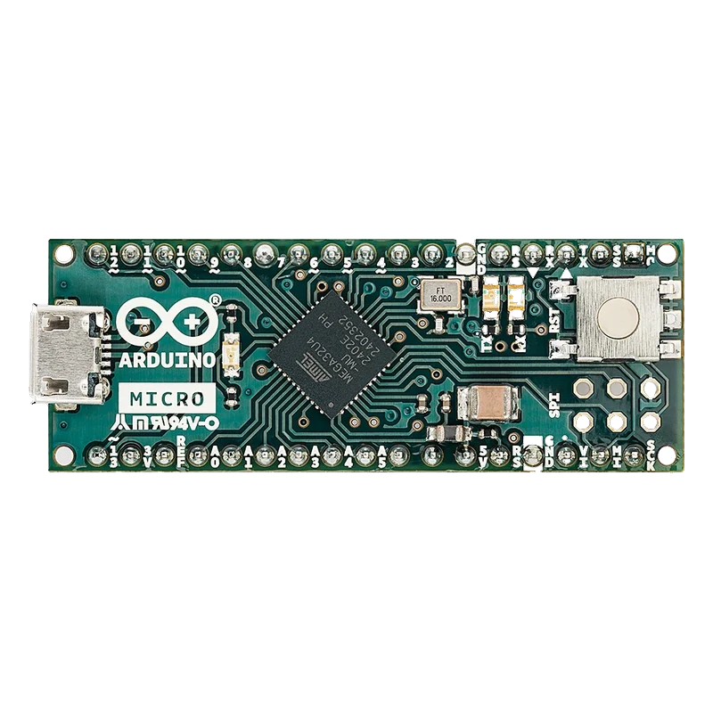
The Arduino Micro is a 48 x 18 mm board that plugs into a breadboard and runs an ATmega32U4 at 16 MHz with 32 KB of flash, 2.5 KB of SRAM and 5 V I/O (Arduino tech specs; ATmega32U4 datasheet, p. 1). Its chip handles USB itself, so the Micro can be a USB keyboard or mouse, with Serial on USB and Serial1 on D0/D1 (Arduino Leonardo and Micro guide). It brings out 20 digital pins, 7 PWM and 12 analog inputs, with I2C on D2/D3 and SPI on D14 to D17 (Arduino Micro pinout).
The Micro is the Leonardo shrunk to a two-row module: the same ATmega32U4, the same Caterina bootloader and the same pin numbers, without the barrel jack and shield headers (Arduino Micro tech specs and pinout). It is the board to pick for a small HID device, such as a macro pad or a controller, that has to fit in a case or on a breadboard.
Like the Leonardo, the Micro runs USB in the same chip as your sketch. Resetting it drops the COM port and brings it back, Serial means the USB link, and the hardware UART on D0/D1 is Serial1. Opening the Serial Monitor does not reset the board, so wait for Serial if setup() prints something you need (Arduino Leonardo and Micro guide).
One difference from the Leonardo is handy on a breadboard: the SPI pins are on the header as D14 (MISO), D15 (SCK), D16 (MOSI) and D17 (SS), not only on an ICSP connector. D17 also drives the RX LED (Arduino Micro pinout).
Arduino Micro pinout
| Pin | Function | Type |
|---|---|---|
| D13 | PWM, Digital, LED_BUILTIN5 V | bidirectional |
| 3V3 | +3V33.3 V | power out |
| AREF | ADC reference0 V to 5 V | power in |
| A0 | ADC7, Digital5 V | bidirectional |
| A1 | ADC6, Digital5 V | bidirectional |
| A2 | ADC5, Digital5 V | bidirectional |
| A3 | ADC4, Digital5 V | bidirectional |
| A4 | ADC1, Digital5 V | bidirectional |
| A5 | ADC0, Digital5 V | bidirectional |
| NC | NC | passive |
| NC-2 | NC | passive |
| 5V | +5V5 V | power out |
| RESET | Reset (active low)5 V | input |
| GND | GND | power in |
| VIN | VIN7 V to 12 V recommended | power in |
| D14 | SPI MISO, Digital5 V | bidirectional |
| D15 | SPI SCK, Digital5 V | bidirectional |
| D12 | ADC9 (A11), Digital5 V | bidirectional |
| D11 | PWM, Digital5 V | bidirectional |
| D10 | PWM, ADC13 (A10), Digital5 V | bidirectional |
| D9 | PWM, ADC12 (A9), Digital5 V | bidirectional |
| D8 | ADC11 (A8), Digital5 V | bidirectional |
| D7 | INT6, Digital5 V | bidirectional |
| D6 | PWM, ADC10 (A7), Digital5 V | bidirectional |
| D5 | PWM, Digital5 V | bidirectional |
| D4 | ADC8 (A6), Digital5 V | bidirectional |
| D3 | I2C SCL, PWM, INT0, Digital5 V | bidirectional |
| D2 | I2C SDA, INT1, Digital5 V | bidirectional |
| GND-2 | GND | power in |
| RESET-2 | Reset (active low)5 V | input |
| D0 | UART RX (Serial1), INT2, Digital5 V | bidirectional |
| D1 | UART TX (Serial1), INT3, Digital5 V | bidirectional |
| D17 | SPI SS, Digital5 V | bidirectional |
| D16 | SPI MOSI, Digital5 V | bidirectional |
Arduino Micro code
Every example here compiles for its board.
// Arduino Micro on Arduino Micro: wiring and a free simulation at https://www.tinkered.ai/components/arduino-micro
// Arduino Micro: a joystick mouse.
// KY-023 joystick: VRx to A0, VRy to A1, SW to D7, +5V to 5V, GND to GND.
// A switch from D4 to GND turns the mouse on; with it open the board only prints.
#include <Mouse.h>

const int X_PIN = A0;
const int Y_PIN = A1;
const int CLICK_PIN = 7;     // joystick push switch, active LOW
const int ENABLE_PIN = 4;    // close to GND to let the board move the cursor
const int LED_PIN = LED_BUILTIN;   // D13
const int DEAD_ZONE = 40;    // ADC counts around the centre that count as still
const int MAX_STEP = 8;      // pixels per update at full tilt

int toStep(int raw) {
  int offset = raw - 512;    // 10-bit ADC, 0 to 1023 for 0 to 5 V
  if (abs(offset) < DEAD_ZONE) return 0;
  return map(offset, -512, 511, -MAX_STEP, MAX_STEP);
}

void setup() {
  pinMode(CLICK_PIN, INPUT_PULLUP);
  pinMode(ENABLE_PIN, INPUT_PULLUP);
  pinMode(LED_PIN, OUTPUT);
  Serial.begin(115200);      // USB serial (CDC)
  Mouse.begin();
}

void loop() {
  int rawX = analogRead(X_PIN);
  int rawY = analogRead(Y_PIN);
  int dx = toStep(rawX);
  int dy = toStep(rawY);
  bool enabled = digitalRead(ENABLE_PIN) == LOW;
  bool clicking = digitalRead(CLICK_PIN) == LOW;

  digitalWrite(LED_PIN, enabled ? HIGH : LOW);
  if (enabled) {
    if (dx != 0 || dy != 0) Mouse.move(dx, dy, 0);
    if (clicking && !Mouse.isPressed(MOUSE_LEFT)) Mouse.press(MOUSE_LEFT);
    if (!clicking && Mouse.isPressed(MOUSE_LEFT)) Mouse.release(MOUSE_LEFT);
  } else if (Mouse.isPressed(MOUSE_LEFT)) {
    Mouse.release(MOUSE_LEFT);
  }

  static unsigned long lastPrint = 0;
  if (millis() - lastPrint >= 250) {
    lastPrint = millis();
    Serial.print("x=");
    Serial.print(rawX);
    Serial.print(" y=");
    Serial.print(rawY);
    Serial.print(" mouse ");
    Serial.println(enabled ? "on" : "off");
  }
  delay(10);
}
Before you wire it
- Read modules on D0/D1 with Serial1; Serial is the USB port (Arduino Leonardo and Micro guide).
- Gate Mouse and Keyboard calls behind a switch so the board can always be reprogrammed.
- Use D2 (SDA) and D3 (SCL) for I2C and D14 to D17 for SPI (Arduino Micro pinout).
- Power 3.3 V modules from their own regulator if they need more than the 3.3V pin's 50 mA (Arduino Micro pinout).
- Never connect a 3.3 V-only module's inputs straight to the Micro's 5 V outputs.
- Never draw more than 40 mA from one pin or 200 mA from the whole chip (ATmega32U4 datasheet, p. 383).
- Never feed VIN and the 5V pin from two different supplies at once.
- Pressing RESET starts the bootloader for about 8 seconds with the L LED pulsing; after power-up the sketch starts straight away (Arduino Caterina bootloader, Caterina.c).
- The IDE resets the board for an upload by opening its USB port at 1200 baud and closing it (Arduino Leonardo and Micro guide).
- D17/SS also drives the RX LED, so the LED flickers while SPI runs (Arduino Micro pinout).
- With AREF left open, analogRead() spans 0 to 5 V in 1024 steps, about 4.9 mV a count.
Specifications
- Microcontroller
- ATmega32U4, 8-bit AVR at 16 MHzArduino Micro tech specs (A000053), docs.arduino.cc
- Memory
- 32 KB flash (28,672 bytes for sketches), 2.5 KB SRAM, 1 KB EEPROMMicrochip ATmega16U4/32U4 datasheet (Atmel-7766J, 04/2016), p. 1; ArduinoCore-avr boards.txt, micro entry
- USB
- Native full-speed USB 2.0 device in the chip, micro USB connectorMicrochip ATmega16U4/32U4 datasheet (Atmel-7766J, 04/2016), p. 1; Arduino Micro tech specs (A000053), docs.arduino.cc
- I/O voltage
- 5 V logicArduino Micro tech specs (A000053), docs.arduino.cc
- Current per I/O pin
- 40 mA absolute maximum per pin, 200 mA through VCC and GND pins; Arduino rates 10 mA DC per pinMicrochip ATmega16U4/32U4 datasheet (Atmel-7766J, 04/2016), p. 383; Arduino Micro tech specs (A000053), docs.arduino.cc
- Pins
- 20 digital I/O, 7 PWM, 12 analog inputsArduino Micro tech specs (A000053), docs.arduino.cc
- ADC
- 10-bit, 12 channelsMicrochip ATmega16U4/32U4 datasheet (Atmel-7766J, 04/2016), p. 2
- Power inputs
- USB or VIN, 7 V to 12 V recommendedArduino Micro tech specs (A000053), docs.arduino.cc
- 3.3V pin
- 50 mA maximumArduino Micro full pinout (A000053, updated 10/11/2020)
- Size
- 48 x 18 mm, 13 gArduino Micro tech specs (A000053), docs.arduino.cc
From the Arduino Micro documentation (A000053), published by Arduino (Microchip ATmega32U4).
Common mistakes
Using Serial for a module on RX/TX
Serial is the USB port on the Micro. A GPS, Bluetooth or RS-485 module wired to D0/D1 is on Serial1 (Arduino Leonardo and Micro guide).
Getting locked out by a HID sketch
If a sketch sends keys or moves the mouse constantly, hold RESET, click Upload, and release RESET when the IDE shows Uploading, so the bootloader catches the new sketch (Arduino Leonardo and Micro guide).
Looking for I2C on A4/A5
On the Micro, A4 and A5 are analog inputs only; I2C is D2 (SDA) and D3 (SCL) (Arduino Micro pinout).
Assuming setup() output will show
The Micro does not reset when the Serial Monitor opens, so lines printed in setup() are lost unless the sketch waits with while (!Serial) {} (Arduino Leonardo and Micro guide).
Arduino Micro questions
What is the difference between the Arduino Micro and the Leonardo?
Both use the ATmega32U4 with the same pin numbers and native USB. The Micro is 48 x 18 mm for breadboards and has no barrel jack or shield headers, while the Leonardo is Uno-shaped (Arduino tech specs). The Micro also brings SPI out on D14 to D17 instead of only on an ICSP header (Arduino Micro pinout).
Arduino Micro vs Nano: which should I buy?
Both fit a breadboard. The classic Nano has an ATmega328P with 2 KB of SRAM and a separate USB-serial chip, so it can't act as a USB keyboard or mouse. The Micro's ATmega32U4 has 2.5 KB of SRAM and USB on chip (ATmega32U4 datasheet, p. 1), so pick it for HID projects.
How do I reset the Arduino Micro into the bootloader?
Press RESET once: the bootloader then waits about 8 seconds for an upload (Caterina.c). If the port never appears, hold RESET, click Upload and release it when the IDE shows Uploading (Arduino Leonardo and Micro guide).
Is the Arduino Micro 5 V or 3.3 V?
It is a 5 V board: the ATmega32U4 runs at 5 V and 16 MHz and its pins swing to 5 V (Arduino tech specs). A 3.3V pin supplies up to 50 mA for small modules (Arduino Micro pinout), but 3.3 V-only inputs still need level shifting.
Which pins of the Arduino Micro are analog?
A0 to A5, plus D4, D6, D8, D9, D10 and D12, which read as A6 to A11: 12 inputs on a 10-bit ADC (Arduino Micro pinout; ATmega32U4 datasheet, p. 2).
Build something with the Arduino Micro
- Build this
USB volume knob
A rotary encoder that turns the computer's volume up and down.
- Build this
Breadboard joystick mouse
A thumb joystick and a switch that move the cursor and click.
- Build this
Stream deck mini
A few keys that send keyboard shortcuts to streaming software.
This page as plain Markdown, for ChatGPT, Claude or your own agent. /components/arduino-micro.md