XL4005
A 5 A adjustable buck converter module that steps 5 V to 32 V down to 0.8 V to 30 V at up to about 90 % efficiency, set with a multi-turn trimmer.
- Input voltage5 V to 32 V (35 V absolute maximum)
- Output voltage0.8 V to 30 V, adjustable
- Output currentUp to 5 A
- Switching frequency300 kHz typical (240 kHz to 360 kHz)
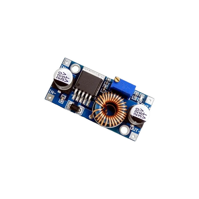
The XL4005 module is a switching step-down converter: 5 V to 32 V in, 0.8 V to 30 V out, up to 5 A, switching at 300 kHz with about 90 % efficiency at 12 V to 5 V (XLSEMI XL4005 datasheet Rev 2.5, pp. 1, 5). A 25-turn trimmer sets the output (Addicore XL4005 module page). Set it with a multimeter before you connect a board: the chip can run at 100 % duty, so a misset trimmer passes nearly the full input voltage through.
Where a 7805 or LM317 burns the voltage difference as heat, the XL4005 chops the input at 300 kHz and smooths it through an inductor, so most of the power reaches the load: XLSEMI quotes 90 % efficiency converting 12 V to 5 V (datasheet, p. 5). That makes it the module to reach for when a 12 V or 24 V supply must feed a few amps at 5 V, for example a Raspberry Pi, a servo bank or LED strips.
The output is set by a feedback divider against a 0.8 V reference (datasheet, pp. 2, 5); on the module that divider includes a 25-turn trimmer (Addicore XL4005 page). Because the chip's maximum duty cycle is 100 % (datasheet, p. 1), the output can come within a fraction of a volt of the input when the trimmer is turned high.
The module's power LED sits on the output with a 1 kOhm resistor, so Addicore advises removing it or raising the resistor above 12 V output. The chip itself includes thermal shutdown and an 8 A switch current limit (datasheet, p. 5).
XL4005 pinout
| Pin | Function | Type |
|---|---|---|
| IN_PLUS | IN+5 V to 32 V | power in |
| IN_MINUS | IN- | power in |
| OUT_PLUS | OUT+0.8 V to 30 V, up to 5 A | power out |
| OUT_MINUS | OUT- | power out |
How to wire the XL4005
Pin by pin, for the board you have.
| XL4005 | Arduino Uno | Note |
|---|---|---|
| IN_PLUS | 12 V supply + | Also to A0 through 10 kOhm, with 3.3 kOhm from A0 to GND, to monitor the input. |
| IN_MINUS | 12 V supply - | |
| OUT_PLUS | 5V | Only after setting the output to 5.0 V with a multimeter and no load. |
| OUT_MINUS | GND |
- Set and measure the output before connecting the Uno: a trimmer turned high sends nearly the full 12 V into the 5V pin.
- Unplug USB while the module feeds the 5V pin.
| XL4005 | ESP32 DevKit V1 | Note |
|---|---|---|
| IN_PLUS | 12 V supply + | Also to GPIO34 through 10 kOhm, with 2.2 kOhm from GPIO34 to GND (12 V reads 2.16 V). |
| IN_MINUS | 12 V supply - | |
| OUT_PLUS | VIN | Output set to 5.0 V first. |
| OUT_MINUS | GND |
- Never connect OUT+ to 3V3. Feed 5 V to VIN and let the DevKit's regulator make 3.3 V.
- Keep the input below about 17 V with this divider so GPIO34 stays under 3.1 V.
| XL4005 | Raspberry Pi Pico | Note |
|---|---|---|
| IN_PLUS | 12 V supply + | Also to GP26 through 10 kOhm, with 2.2 kOhm from GP26 to GND. |
| IN_MINUS | 12 V supply - | |
| OUT_PLUS | VSYS | Output set to 5.0 V first, through a Schottky diode (anode at the module) so USB can stay connected. |
| OUT_MINUS | GND |
- VSYS accepts 1.8 V to 5.5 V (Raspberry Pi Pico datasheet, p. 9); measure the module's output before connecting.
- A second supply into VSYS goes through a Schottky diode (Pico datasheet, p. 22).
XL4005 code
Every example here compiles for its board.
// XL4005 on Arduino Uno: wiring and a free simulation at https://www.tinkered.ai/components/xl4005
// XL4005 feeding an Arduino Uno's 5V pin from a 12 V supply; the input is measured on A0
// through a 10k (top) / 3.3k (bottom) divider. Warns when the supply sags.
const int VIN_SENSE = A0;
const float DIVIDER = (10.0 + 3.3) / 3.3;
const float LOW_INPUT = 6.0; // the XL4005 needs headroom above its 5 V output

void setup() {
  Serial.begin(115200);
  Serial.println("XL4005 supply monitor");
}

void loop() {
  float vin = analogRead(VIN_SENSE) * 5.0 / 1023.0 * DIVIDER;
  Serial.print("Input: ");
  Serial.print(vin, 2);
  Serial.println(vin < LOW_INPUT ? " V  LOW" : " V");
  delay(1000);
}
// XL4005 on ESP32 DevKit V1: wiring and a free simulation at https://www.tinkered.ai/components/xl4005
// XL4005 feeding an ESP32 DevKit V1 on VIN at 5 V; the 12 V input is measured on GPIO34
// through a 10k (top) / 2.2k (bottom) divider.
const int VIN_SENSE = 34;
const float DIVIDER = (10.0 + 2.2) / 2.2;
const float LOW_INPUT = 6.0;

void setup() {
  Serial.begin(115200);
  Serial.println("XL4005 supply monitor");
}

void loop() {
  float vin = analogReadMilliVolts(VIN_SENSE) / 1000.0 * DIVIDER;
  Serial.printf("Input: %.2f V%s\n", vin, vin < LOW_INPUT ? "  LOW" : "");
  delay(1000);
}
// XL4005 on Raspberry Pi Pico: wiring and a free simulation at https://www.tinkered.ai/components/xl4005
// XL4005 feeding a Raspberry Pi Pico on VSYS (through a Schottky diode); the 12 V input is
// measured on GP26 (ADC0) through a 10k (top) / 2.2k (bottom) divider.
const int VIN_SENSE = 26;
const float DIVIDER = (10.0 + 2.2) / 2.2;
const float LOW_INPUT = 6.0;

void setup() {
  Serial.begin(115200);
  analogReadResolution(12); // 0..4095 over 0..3.3 V
  Serial.println("XL4005 supply monitor");
}

void loop() {
  float vin = analogRead(VIN_SENSE) * 3.3 / 4095.0 * DIVIDER;
  Serial.print("Input: ");
  Serial.print(vin, 2);
  Serial.println(vin < LOW_INPUT ? " V  LOW" : " V");
  delay(1000);
}
Before you wire it
- Set the output with a multimeter and no load before connecting anything: turn the 25-turn trimmer until OUT+ reads the voltage you want.
- Keep the input between 5 V and 32 V (datasheet, p. 5), and above the output by enough to regulate under load.
- Use wires and connectors rated for the current; at 5 A, thin jumper wires heat up and drop voltage.
- Above 12 V output, remove the power LED or raise its 1 kOhm resistor (Addicore XL4005 page).
- Never connect a board before measuring the output: the 100 % maximum duty cycle (datasheet, p. 1) lets a high trimmer setting pass almost the whole input voltage.
- Never exceed 35 V at the input (datasheet, p. 4).
- Never swap IN and OUT: the module only converts from IN to OUT.
- Never adjust the trimmer while a board is connected; a slip of the screwdriver can overshoot.
- The output follows VOUT = 0.8 V x (1 + Rtop/Rbottom) through the feedback divider (datasheet, p. 2); the module's trimmer is part of that divider.
- At 300 kHz the output carries a small switching ripple; add a 100 µF electrolytic and a 0.1 µF ceramic at the load for sensitive circuits.
- Quiescent current is about 3 mA (datasheet, p. 5), so the module draws a little even with no load; for battery projects, switch its input.
- The chip's switch current limit is 8 A and it has thermal shutdown (datasheet, p. 5); at 5 A continuous the module gets hot, so give it airflow.
- For 5 V at a few amps from 12 V, this module wastes about a tenth of the power where a linear 7805 would waste more than half.
Specifications
- Input voltage
- 5 V to 32 V (35 V absolute maximum)XLSEMI XL4005 datasheet Rev 2.5, pp. 4, 5
- Output voltage
- 0.8 V to 30 V, adjustableXLSEMI XL4005 datasheet Rev 2.5, p. 1
- Output current
- Up to 5 AXLSEMI XL4005 datasheet Rev 2.5, p. 1
- Switching frequency
- 300 kHz typical (240 kHz to 360 kHz)XLSEMI XL4005 datasheet Rev 2.5, p. 5
- Feedback reference
- 0.8 V (0.776 V to 0.824 V)XLSEMI XL4005 datasheet Rev 2.5, p. 5
- Efficiency
- 90 % typical at 12 V in, 5 V out, 5 AXLSEMI XL4005 datasheet Rev 2.5, p. 5
- Maximum duty cycle
- 100 %XLSEMI XL4005 datasheet Rev 2.5, p. 1
- Switch current limit
- 8 AXLSEMI XL4005 datasheet Rev 2.5, p. 5
- Module
- 25-turn trimmer; power LED with 1 kOhm on the output (remove above 12 V out)Addicore XL4005 Step-Down Buck Converter product page
From the XL4005 5A 300KHz 32V Buck DC to DC Converter datasheet, Rev 2.5, published by XLSEMI.
Common mistakes
Powering a board before setting the voltage
Modules ship with the trimmer anywhere. With 100 % maximum duty (datasheet, p. 1) the output can sit near the input, so 12 V reaches a 5 V pin. Always set and measure first.
Turning the trimmer the wrong way for minutes
The 25-turn trimmer (Addicore page) changes the voltage slowly and slips silently at its ends. Watch the meter while turning; if nothing changes, turn the other way.
Expecting 5 A from a small input supply
The module moves power, not current: 5 V at 5 A is 25 W, which at 90 % efficiency (datasheet, p. 5) needs about 28 W from the input, roughly 2.3 A at 12 V.
LED burning out at high output
The power LED and its 1 kOhm resistor sit across the output. Above 12 V the resistor runs hot; Addicore recommends removing the LED or fitting a larger resistor.
XL4005 questions
XL4005 vs LM2596: which buck module should I use?
The XL4005 handles 5 A at 300 kHz (datasheet, p. 1), the LM2596 module 2 to 3 A at 150 kHz. For a Raspberry Pi, servo banks or LED strips at several amps, the XL4005; for small loads either works.
How do I set the output voltage?
Power the input, leave the output unloaded, put a multimeter on OUT+ and OUT-, and turn the 25-turn trimmer until it reads the target. Then connect the load and check again.
What is the minimum input voltage?
5 V (datasheet, p. 5), and the input must stay above the output to regulate. For a 5 V output, feed 7 V or more for good regulation under load.
Can the XL4005 power an ESP32 or Raspberry Pi Pico?
Yes: set it to 5 V and feed the ESP32's VIN or the Pico's VSYS (through a Schottky diode if USB may be connected). Never feed their 3.3 V pins from it.
Build something with the XL4005
- Build this
12 V to 5 V supply for servos
Power a bank of servos from a 12 V battery.
- Build this
Car USB charger
Turn a car's 12 V into a USB 5 V outlet with voltage monitoring.
- Build this
Solar node power
Run a sensor node from a 12 V solar battery.
This page as plain Markdown, for ChatGPT, Claude or your own agent. /components/xl4005.md