LM7805
The classic fixed 5 V linear regulator in a TO-220 package, turning 7.5 V to 20 V into a regulated 5 V at up to 1.5 A.
- Output voltage4.8 V to 5.2 V at 25 °C; 4.75 V to 5.25 V over load, line and temperature
- Output currentUp to 1.5 A; short-circuit current 2.1 A, peak 2.4 A (typical, 25 °C)
- Minimum input for regulation7.5 V (at up to 1 A, 25 °C)
- Dropout voltage2 V typical at 1 A
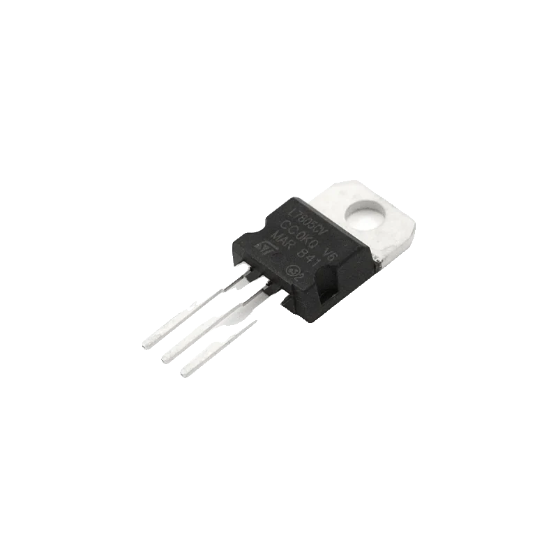
The LM7805 is a three-pin 5 V regulator: pin 1 is INPUT, pin 2 GND (and the tab), pin 3 OUTPUT, and it delivers up to 1.5 A (TI LM340/LM7805 datasheet SNOSBT0L, pp. 1, 3). It needs at least 7.5 V in to hold regulation and drops about 2 V at 1 A (p. 6), with 0.22 µF on the input and 0.1 µF on the output. Everything above 5 V turns into heat: 12 V in at 0.5 A is 3.5 W, far beyond what a bare TO-220 sheds at 54 °C/W (p. 4), so plan a heat sink.
The 7805 has powered hobby projects for decades because it needs almost nothing: input, ground, output and two small capacitors. TI's version holds 4.8 V to 5.2 V at 25 °C and 4.75 V to 5.25 V across its full load and line range (datasheet, p. 6), with internal current limiting, thermal shutdown and safe-area protection (p. 1).
Being linear, it burns the difference between input and output as heat: P = (VIN - 5 V) x I. In free air the TO-220 has a junction-to-ambient resistance of 54 °C/W (datasheet, p. 4), so about 1.5 W already brings the junction near 100 °C above room temperature. For a 12 V battery feeding an ESP32 or a few hundred milliamps of servos, a buck converter wastes far less.
It also needs headroom: TI specifies 7.5 V at the input to keep regulating at up to 1 A (datasheet, p. 6). A 6 V battery pack or a 7 V supply under load lets the output sag. The absolute maximum input is 35 V (p. 4).
LM7805 pinout
| Pin | Function | Type |
|---|---|---|
| INPUT | 1 (IN)7.5 V to 20 V for full regulation, 35 V absolute maximum | power in |
| GND | 2 (GND) | power in |
| OUTPUT | 3 (OUT)5 V, up to 1.5 A | power out |
How to wire the LM7805
Pin by pin, for the board you have.
| LM7805 | Arduino Uno | Note |
|---|---|---|
| INPUT | Supply + (9 V to 12 V) | 0.22 µF ceramic from INPUT to GND at the regulator. Also to A0 through a 10 kOhm resistor, with 3.3 kOhm from A0 to GND, to measure the supply. |
| GND | Supply - and GND | |
| OUTPUT | 5V | 0.1 µF ceramic from OUTPUT to GND at the regulator. |
- Unplug USB while the regulator feeds the Uno's 5V pin, so two 5 V sources never fight.
- Feeding the 5V pin bypasses the Uno's own regulator and its protection; double-check the 7805's pinout before powering up, since a reversed part puts the raw supply on 5V.
- Fit a heat sink if (VIN - 5) x current exceeds about 1 W.
| LM7805 | ESP32 DevKit V1 | Note |
|---|---|---|
| INPUT | Supply + (9 V to 12 V) | 0.22 µF ceramic from INPUT to GND. Also to GPIO34 through a 10 kOhm resistor, with 2.2 kOhm from GPIO34 to GND (12 V reads as 2.16 V). |
| GND | Supply - and GND | |
| OUTPUT | VIN | 0.1 µF ceramic from OUTPUT to GND. The DevKit's own regulator turns VIN into 3.3 V. |
- Never connect the 7805's 5 V output to the 3V3 pin.
- Keep the supply under about 17 V with this 10 kOhm/2.2 kOhm divider so GPIO34 stays below 3.1 V; use a larger top resistor for higher voltages.
- Unplug USB while powering VIN from the regulator, unless your board isolates the two with a diode.
| LM7805 | Raspberry Pi Pico | Note |
|---|---|---|
| INPUT | Supply + (9 V to 12 V) | 0.22 µF ceramic from INPUT to GND. Also to GP26 through a 10 kOhm resistor, with 2.2 kOhm from GP26 to GND. |
| GND | Supply - and GND | |
| OUTPUT | VSYS | Through a Schottky diode (anode at the 7805, cathode at VSYS) so USB and the regulator can both be connected. 0.1 µF from OUTPUT to GND. |
- VSYS accepts 1.8 V to 5.5 V (Raspberry Pi Pico datasheet, p. 9); never feed the regulator's input or any voltage above 5.5 V to it.
- Keep GP26 under 3.3 V: the ADC pins have a diode to the 3.3 V rail (Pico datasheet, p. 20), so the divider must scale the supply down before the Pico is powered.
LM7805 code
Every example here compiles for its board.
// LM7805 on Arduino Uno: wiring and a free simulation at https://www.tinkered.ai/components/lm7805
// LM7805 powering an Arduino Uno through its 5V pin; the raw supply is measured on A0
// through a 10k (top) / 3.3k (bottom) divider, so A0 sees VIN x 3.3 / 13.3.
const int VIN_SENSE = A0;
const float DIVIDER = (10.0 + 3.3) / 3.3; // about 4.03

void setup() {
  Serial.begin(115200);
  Serial.println("LM7805 supply monitor");
}

void loop() {
  int raw = analogRead(VIN_SENSE);         // 10-bit, referenced to the 7805's 5 V
  float vin = raw * 5.0 / 1023.0 * DIVIDER;
  float headroom = vin - 5.0;              // the 7805 needs about 2.5 V of it
  Serial.print("Supply: ");
  Serial.print(vin, 2);
  Serial.print(" V, headroom ");
  Serial.print(headroom, 2);
  Serial.println(vin < 7.5 ? " V  (below 7.5 V: 5 V may sag)" : " V");
  delay(1000);
}
// LM7805 on ESP32 DevKit V1: wiring and a free simulation at https://www.tinkered.ai/components/lm7805
// LM7805 feeding an ESP32 DevKit V1 on VIN; the raw supply is measured on GPIO34
// through a 10k (top) / 2.2k (bottom) divider, so GPIO34 sees VIN x 2.2 / 12.2.
const int VIN_SENSE = 34;
const float DIVIDER = (10.0 + 2.2) / 2.2; // about 5.55

void setup() {
  Serial.begin(115200);
  Serial.println("LM7805 supply monitor");
}

void loop() {
  uint32_t mv = analogReadMilliVolts(VIN_SENSE); // calibrated millivolts at the pin
  float vin = mv / 1000.0 * DIVIDER;
  Serial.printf("Supply: %.2f V%s\n", vin, vin < 7.5 ? "  (below 7.5 V: 5 V may sag)" : "");
  delay(1000);
}
// LM7805 on Raspberry Pi Pico: wiring and a free simulation at https://www.tinkered.ai/components/lm7805
// LM7805 feeding a Raspberry Pi Pico on VSYS (through a Schottky diode); the raw supply
// is measured on GP26 (ADC0) through a 10k (top) / 2.2k (bottom) divider.
const int VIN_SENSE = 26;
const float DIVIDER = (10.0 + 2.2) / 2.2; // about 5.55

void setup() {
  Serial.begin(115200);
  analogReadResolution(12); // 0..4095 over 0..3.3 V
  Serial.println("LM7805 supply monitor");
}

void loop() {
  int raw = analogRead(VIN_SENSE);
  float vin = raw * 3.3 / 4095.0 * DIVIDER;
  Serial.print("Supply: ");
  Serial.print(vin, 2);
  Serial.println(vin < 7.5 ? " V  (below 7.5 V: 5 V may sag)" : " V");
  delay(1000);
}
Before you wire it
- Check the pinout before soldering: on the TO-220, pin 1 is INPUT, pin 2 GND and pin 3 OUTPUT (TI datasheet, p. 3).
- Fit 0.22 µF from INPUT to GND and 0.1 µF from OUTPUT to GND, close to the pins (datasheet, p. 6); add a 10 µF to 100 µF electrolytic on the input when the supply wires are long.
- Work out the heat: (VIN - 5 V) x current. Above about 1 W, bolt it to a heat sink; at 54 °C/W in free air (datasheet, p. 4) 1.5 W heats the junction by about 80 °C.
- Give it at least 7.5 V at the input (datasheet, p. 6), or the output falls below 5 V.
- Never exceed 35 V at the input (datasheet, p. 4).
- Never use it to power motors or servos from a 12 V battery without a heat sink; at 1 A it burns 7 W.
- Never touch the tab expecting it to be isolated: it is ground on the TO-220 (datasheet, p. 1), so insulate it from a heat sink tied to anything else.
- Never connect its output to a board's 3.3 V pin.
- The regulator only removes voltage: VIN at 12 V and a 300 mA load means 7 V x 0.3 A = 2.1 W of heat, about 113 °C of rise in free air at 54 °C/W (datasheet, p. 4). A clip-on TO-220 heat sink or a buck converter fixes it.
- The output tolerance over load, line and temperature is 4.75 V to 5.25 V (datasheet, p. 6), fine for logic and sensors.
- Internal current limiting (2.1 A typical short-circuit current) and thermal shutdown protect the part (datasheet, pp. 1, 6), but a regulator cycling in thermal shutdown makes a board reset again and again.
- If a large output capacitor can stay charged after the input is removed, a reverse diode from OUTPUT to INPUT protects the regulator.
- For a Pico, feed VSYS through a Schottky diode so the regulator and USB OR together safely (Raspberry Pi Pico datasheet, p. 22).
Specifications
- Output voltage
- 4.8 V to 5.2 V at 25 °C; 4.75 V to 5.25 V over load, line and temperatureTI LM340/LM7805 datasheet SNOSBT0L, p. 6
- Output current
- Up to 1.5 A; short-circuit current 2.1 A, peak 2.4 A (typical, 25 °C)TI LM340/LM7805 datasheet SNOSBT0L, pp. 1, 6
- Minimum input for regulation
- 7.5 V (at up to 1 A, 25 °C)TI LM340/LM7805 datasheet SNOSBT0L, p. 6
- Dropout voltage
- 2 V typical at 1 ATI LM340/LM7805 datasheet SNOSBT0L, p. 6
- Absolute maximum input
- 35 V DCTI LM340/LM7805 datasheet SNOSBT0L, p. 4
- Quiescent current
- 8 mA maximum at 25 °CTI LM340/LM7805 datasheet SNOSBT0L, p. 6
- Thermal resistance (TO-220)
- 54 °C/W junction to ambient in free air, 4 °C/W junction to caseTI LM340/LM7805 datasheet SNOSBT0L, p. 4
- Capacitors
- 0.22 µF input to ground, 0.1 µF output to ground (as characterized)TI LM340/LM7805 datasheet SNOSBT0L, p. 6
- TO-220 pinout
- 1 INPUT, 2 GND, 3 OUTPUT; tab is groundTI LM340/LM7805 datasheet SNOSBT0L, pp. 1, 3
From the LM340, LM340A and LM7805 Family Wide VIN 1.5-A Fixed Voltage Regulators, SNOSBT0L (revised September 2016), published by Texas Instruments (also ST, onsemi and others).
Common mistakes
Wiring it as IN, OUT, GND
The 78xx order is INPUT, GND, OUTPUT (pins 1, 2, 3; TI datasheet, p. 3). The negative 79xx regulators use a different order, and swapping them puts the raw supply on your board.
No heat sink at 12 V
At 12 V in and 500 mA out the 7805 burns 3.5 W. With 54 °C/W in free air (datasheet, p. 4) it would rise far beyond its limit, so it cycles in thermal shutdown and the board keeps rebooting.
Running it from a 6 V or 7 V source
It needs about 2 V of headroom at 1 A and TI characterizes regulation from 7.5 V up (datasheet, p. 6). Four AA cells or a sagging 7.4 V pack are too low; use a low-dropout regulator or a buck-boost.
Skipping the capacitors
Without the 0.22 µF and 0.1 µF capacitors close to the pins (datasheet, p. 6), long leads can make it oscillate and the output looks noisy on a scope or resets a microcontroller.
LM7805 questions
What is the LM7805 pinout?
With the printed face toward you and the leads down: pin 1 (left) INPUT, pin 2 (middle) GND, pin 3 (right) OUTPUT. The metal tab is connected to ground (TI datasheet, pp. 1, 3).
What is the minimum input voltage for a 7805?
About 7 V at light load and 7.5 V to stay in regulation at up to 1 A, since the dropout is about 2 V (TI datasheet, p. 6). Below that the output follows the input down.
Does the LM7805 need a heat sink?
Whenever (VIN - 5 V) x current goes above about 1 W. The TO-220's 54 °C/W in free air (TI datasheet, p. 4) means 1 W already warms it about 54 °C above ambient; at 2 W or more it needs a real heat sink or a switching regulator instead.
LM7805 vs LM2596 buck module: which should I use?
The LM7805 is simple, quiet and cheap but wastes the excess voltage as heat: from 12 V it throws away more than half the power. An LM2596 buck converter switches instead, so it stays cool at 1 A or more. Use the 7805 for small loads or small voltage drops, the buck for anything more.
Can I power an ESP32 from an LM7805?
Yes: feed the 7805's 5 V into the DevKit's VIN pin, where its own regulator makes 3.3 V. Keep the 7805 cool, since an ESP32 with Wi-Fi draws peaks of several hundred milliamps.
Build something with the LM7805
- Build this
12 V to 5 V supply for a sensor node
Run an Arduino and sensors from a 12 V adapter with a supply-voltage readout.
- Build this
Battery voltage monitor
Watch a 12 V battery while a regulator powers the board.
- Build this
Bench 5 V rail
A protected 5 V rail for breadboard experiments.
This page as plain Markdown, for ChatGPT, Claude or your own agent. /components/lm7805.md