LM317
The classic adjustable linear regulator in TO-220: two resistors set any output from 1.25 V to 37 V at up to 1.5 A.
- Output voltage range1.25 V to 37 V
- Output current10 mA to 1.5 A (recommended)
- Input-to-output voltage3 V to 40 V
- Reference voltage1.25 V typical (1.2 V to 1.3 V)
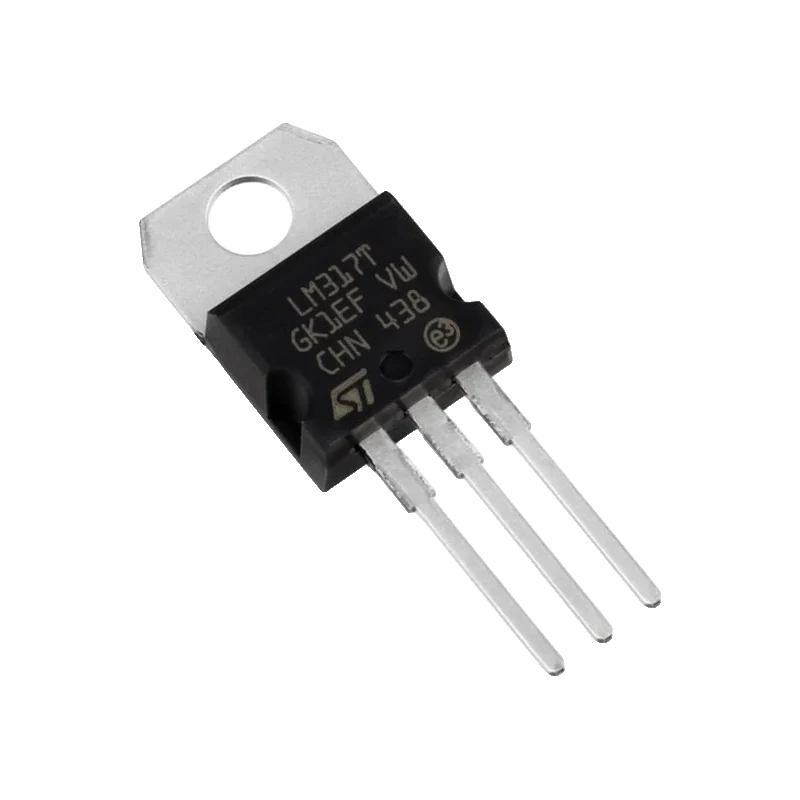
The LM317 is an adjustable linear regulator: it holds 1.25 V between OUTPUT and ADJUST, so VOUT = 1.25 V x (1 + R2/R1) + I_ADJ x R2, with R1 = 240 ohm in TI's reference circuit (TI LM317 datasheet SLVS044Z, p. 1). It delivers 1.25 V to 37 V at up to 1.5 A and needs at least 3 V more at the input than the output (p. 6). On the TO-220, pin 1 is ADJUST, pin 2 OUTPUT (and the tab), pin 3 INPUT (p. 5).
Inside the LM317 a 1.25 V reference sits between OUTPUT and ADJUST. A resistor R1 from OUTPUT to ADJUST therefore carries a fixed current, and the same current through R2 to ground sets how far the output rises above 1.25 V. The tiny 50 µA that flows out of the ADJUST pin (TI datasheet, p. 8) adds a small error term, which is why R1 is kept low, 240 ohm in TI's circuit (p. 1).
TI specifies 3 V to 40 V between input and output and 10 mA to 1.5 A of load (datasheet, p. 6). The minimum load matters: below about 10 mA at high input-to-output voltage the output can drift up (p. 8), which the current through R1 usually covers.
Like the 7805, it turns the voltage difference into heat: (VIN - VOUT) x current. It includes current limiting, about 2.2 A typical with 15 V or less across it (p. 8), and thermal shutdown, but a TO-220 dissipating more than a watt or two needs a heat sink.
LM317 pinout
| Pin | Function | Type |
|---|---|---|
| ADJ | Adjust | input |
| OUT | 2 (OUT)1.25 V to 37 V, up to 1.5 A | power out |
| IN | 3 (IN)At least VOUT + 3 V, at most VOUT + 40 V | power in |
How to wire the LM317
Pin by pin, for the board you have.
| LM317 | Arduino Uno | Note |
|---|---|---|
| IN | 12 V supply + | 0.1 µF ceramic to GND at the pin. |
| ADJ | R1 and R2 junction | R1 = 240 ohm from OUT to ADJ; R2 = 5 kOhm potentiometer (as a variable resistor) from ADJ to GND. |
| OUT | Load + and A0 through 10 kOhm | 1 µF from OUT to GND. 3.3 kOhm from A0 to GND completes the measuring divider. |
- The Uno runs from USB here; only GND is shared with the 12 V supply. The divider keeps A0 under 5 V up to about 20 V.
- The tab is OUTPUT: insulate it from a grounded heat sink.
| LM317 | ESP32 DevKit V1 | Note |
|---|---|---|
| IN | 12 V supply + | 0.1 µF ceramic to GND at the pin. |
| ADJ | R1 and R2 junction | R1 = 240 ohm from OUT to ADJ; R2 = 5 kOhm potentiometer from ADJ to GND. |
| OUT | Load + and GPIO34 through 10 kOhm | 1 µF from OUT to GND. 2.2 kOhm from GPIO34 to GND: 9 V reads as 1.6 V. |
- With 12 V in, the output can reach about 9 V (3 V dropout), which the 10 kOhm/2.2 kOhm divider keeps below 1.7 V at GPIO34. Recalculate the divider for higher supplies.
- Never wire OUT directly to a GPIO or to 3V3.
| LM317 | Raspberry Pi Pico | Note |
|---|---|---|
| IN | 12 V supply + | 0.1 µF ceramic to GND at the pin. |
| ADJ | R1 and R2 junction | R1 = 240 ohm from OUT to ADJ; R2 = 5 kOhm potentiometer from ADJ to GND. |
| OUT | Load + and GP26 through 10 kOhm | 1 µF from OUT to GND. 2.2 kOhm from GP26 to GND. |
- GP26 has a diode to the 3.3 V rail (Raspberry Pi Pico datasheet, p. 20): keep the divider's output under 3.3 V even when the Pico is unpowered.
- Keep the 12 V supply away from VSYS and VBUS; share only GND.
LM317 code
Every example here compiles for its board.
// LM317 on Arduino Uno: wiring and a free simulation at https://www.tinkered.ai/components/lm317
// LM317 bench supply monitor on an Arduino Uno: OUT measured on A0 through 10k (top) / 3.3k (bottom).
const int VOUT_SENSE = A0;
const float DIVIDER = (10.0 + 3.3) / 3.3;
const float R1 = 240.0; // ohms, OUT to ADJ

void setup() {
  Serial.begin(115200);
  Serial.println("LM317 output monitor");
}

void loop() {
  float vout = analogRead(VOUT_SENSE) * 5.0 / 1023.0 * DIVIDER;
  // Solve VOUT = 1.25 * (1 + R2/R1) for the potentiometer's setting (ignoring the 50 uA ADJ current)
  float r2 = (vout / 1.25 - 1.0) * R1;
  Serial.print("VOUT: ");
  Serial.print(vout, 2);
  Serial.print(" V  (R2 about ");
  Serial.print(r2, 0);
  Serial.println(" ohm)");
  delay(500);
}
// LM317 on ESP32 DevKit V1: wiring and a free simulation at https://www.tinkered.ai/components/lm317
// LM317 bench supply monitor on an ESP32 DevKit V1: OUT measured on GPIO34 through 10k (top) / 2.2k (bottom).
const int VOUT_SENSE = 34;
const float DIVIDER = (10.0 + 2.2) / 2.2;
const float R1 = 240.0;

void setup() {
  Serial.begin(115200);
  Serial.println("LM317 output monitor");
}

void loop() {
  float vout = analogReadMilliVolts(VOUT_SENSE) / 1000.0 * DIVIDER;
  float r2 = (vout / 1.25 - 1.0) * R1;
  Serial.printf("VOUT: %.2f V  (R2 about %.0f ohm)\n", vout, r2);
  delay(500);
}
// LM317 on Raspberry Pi Pico: wiring and a free simulation at https://www.tinkered.ai/components/lm317
// LM317 bench supply monitor on a Raspberry Pi Pico (arduino-pico): OUT on GP26 through 10k / 2.2k.
const int VOUT_SENSE = 26;
const float DIVIDER = (10.0 + 2.2) / 2.2;
const float R1 = 240.0;

void setup() {
  Serial.begin(115200);
  analogReadResolution(12); // 0..4095 over 0..3.3 V
  Serial.println("LM317 output monitor");
}

void loop() {
  float vout = analogRead(VOUT_SENSE) * 3.3 / 4095.0 * DIVIDER;
  float r2 = (vout / 1.25 - 1.0) * R1;
  Serial.print("VOUT: ");
  Serial.print(vout, 2);
  Serial.print(" V  (R2 about ");
  Serial.print(r2, 0);
  Serial.println(" ohm)");
  delay(500);
}
Before you wire it
- Check the pinout: ADJUST, OUTPUT, INPUT on pins 1, 2, 3 (TI datasheet, p. 5), unlike the 7805's IN, GND, OUT.
- Keep R1 at about 240 ohm (datasheet, p. 1) so it draws enough current to meet the minimum load, and place it right at the regulator's OUT and ADJ pins.
- Keep at least 3 V between input and output and no more than 40 V (datasheet, p. 6).
- Fit 0.1 µF at the input and 1 µF at the output, as in TI's circuit (datasheet, p. 1).
- Work out the heat, (VIN - VOUT) x I, and add a heat sink above a watt or so.
- Never treat the tab as ground: it is OUTPUT (datasheet, p. 5).
- Never leave ADJUST open: the output then rises toward the input voltage.
- Never wire the LM317's output into a board's 3V3 or 5V pin while you are turning the potentiometer.
- Never expect 1.5 A at a large input-to-output difference: the current limit falls to 0.15 A to 0.4 A at 40 V across it (datasheet, p. 8).
- With R1 = 240 ohm: R2 = 390 ohm gives about 3.3 V, 720 ohm about 5 V and 2.2 kOhm about 12.7 V, from VOUT = 1.25 V x (1 + R2/R1) (datasheet, p. 1).
- The I_ADJ x R2 term is small: 50 µA typical (datasheet, p. 8) through a 5 kOhm potentiometer adds about 0.25 V at the top of its range.
- As a constant-current source for LEDs, put a single resistor R between OUT and ADJ and take the load from ADJ: I = 1.25 V / R.
- A 10 µF capacitor from ADJ to ground improves ripple rejection (datasheet, p. 1, new chip PSRR at C_ADJ = 10 µF); add protection diodes if large output capacitors can discharge back into the regulator.
- The 240 ohm R1 alone draws about 5 mA (1.25 V / 240 ohm), covering the 3.5 mA typical minimum load (datasheet, p. 8).
Specifications
- Output voltage range
- 1.25 V to 37 VTI LM317 datasheet SLVS044Z, pp. 1, 6
- Output current
- 10 mA to 1.5 A (recommended)TI LM317 datasheet SLVS044Z, p. 6
- Input-to-output voltage
- 3 V to 40 VTI LM317 datasheet SLVS044Z, p. 6
- Reference voltage
- 1.25 V typical (1.2 V to 1.3 V)TI LM317 datasheet SLVS044Z, p. 8
- Output formula
- VOUT = 1.25 V x (1 + R2/R1) + I_ADJ x R2, R1 = 240 ohm typicalTI LM317 datasheet SLVS044Z, p. 1
- Adjust pin current
- 50 µA typical, 100 µA maximumTI LM317 datasheet SLVS044Z, p. 8
- Current limit
- 1.5 A minimum, 2.2 A typical with VIN - VOUT at or below 15 V; 0.15 A to 0.4 A at 40 VTI LM317 datasheet SLVS044Z, p. 8
- Minimum load current
- 3.5 mA typical, 10 mA maximum at 40 V input-to-outputTI LM317 datasheet SLVS044Z, p. 8
- TO-220 pinout
- 1 ADJUST, 2 OUTPUT (and tab), 3 INPUTTI LM317 datasheet SLVS044Z, p. 5
From the LM317 3-Pin Adjustable Regulator, SLVS044Z (revised April 2025), published by Texas Instruments (also ST, onsemi and others).
Common mistakes
Using the 7805 pinout
On the LM317 the middle pin and tab are OUTPUT and pin 1 is ADJUST (datasheet, p. 5). Wired as a 7805, it puts the input voltage where you expected ground.
Output too high with no load
With a large R1 or nothing connected, the current through R1 can fall below the minimum load (up to 10 mA at high input-to-output voltage, datasheet p. 8) and the output creeps up. Keep R1 near 240 ohm.
Not enough headroom
The LM317 needs 3 V or more between input and output (datasheet, p. 6). Asking for 9 V from a 9 V battery gives 6 V at best.
Hot regulator
12 V in, 5 V out at 500 mA is 3.5 W. A bare TO-220 cannot shed that; add a heat sink or switch to a buck converter.
LM317 questions
How do I calculate the LM317 output voltage?
VOUT = 1.25 V x (1 + R2/R1) + I_ADJ x R2 (TI datasheet, p. 1). With R1 = 240 ohm, R2 = 720 ohm gives 5 V and R2 = 390 ohm about 3.3 V; the I_ADJ term adds a few tens of millivolts.
What is the LM317 pinout?
On the TO-220, facing the print: pin 1 ADJUST, pin 2 OUTPUT, pin 3 INPUT; the tab is OUTPUT (datasheet, p. 5).
What is the dropout voltage of the LM317?
TI specifies operation with 3 V to 40 V between input and output (datasheet, p. 6). Plan for at least 3 V of headroom; for lower dropout use an LDO such as the AMS1117.
LM317 or buck converter?
The LM317 gives a clean, quiet output and is easy to adjust, but burns (VIN - VOUT) x I as heat. A buck converter such as the LM2596 module wastes far less at large voltage drops or currents.
How much current can an LM317 supply?
Up to 1.5 A in the recommended range (datasheet, p. 6), with a typical current limit of 2.2 A when the drop across it is 15 V or less. At larger drops the limit falls, and heat usually limits it first.
Build something with the LM317
- Build this
Bench power supply with voltmeter
Adjust 1.25 V to 9 V from a 12 V adapter and display it.
- Build this
LED constant-current driver
Drive a 1 W LED at a fixed current.
- Build this
Battery charger supply
A current-limited supply for charging NiMH packs.
This page as plain Markdown, for ChatGPT, Claude or your own agent. /components/lm317.md