ULN2803A
An 18-pin array of eight Darlington drivers with clamp diodes, letting GPIOs sink up to 500 mA per channel from loads of up to 50 V.
- Output voltage50 V maximum (output sustaining voltage)
- Output current500 mA per channel absolute maximum
- Recommended output current (DIP)Up to 347 mA per channel at 10 % duty, 123 mA at 50 % duty (25 ms pulses, -40 to 85 °C)
- Saturation voltage0.9 V typ at 100 mA, 1.1 V at 200 mA, 1.3 V at 350 mA
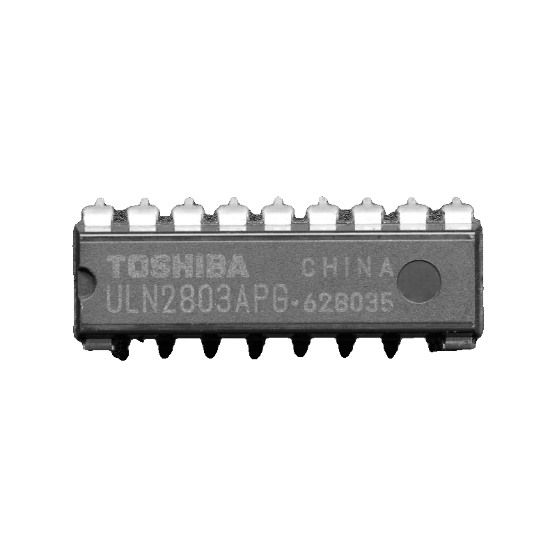
The ULN2803A packs eight Darlington low-side switches with built-in clamp diodes: each output sinks up to 500 mA and withstands 50 V (Toshiba ULN2803APG datasheet, pp. 1, 2). Inputs 1 to 8 face outputs 18 to 11, GND is pin 9 and COM, the clamp diodes' common, pin 10 goes to the load supply. A 5 V pin switches it fully on; from 3.3 V Toshiba's tables guarantee turn-on up to 300 mA per channel (p. 4), and the outputs drop about 1 V (p. 4).
Each of the eight channels is a Darlington pair with a 2.7 kOhm input resistor sized for TTL and 5 V CMOS (Toshiba datasheet, p. 1), an open-collector output and a diode from the output to the common COM pin. Wire the load from its positive supply to an output, tie COM to that same supply, and the diodes catch the spike when a relay or solenoid turns off.
It is the eight-channel big brother of the ULN2003 used on stepper boards, and the quickest way to drive relays, solenoids, small lamps, LED strings or a unipolar stepper from a microcontroller. Like any Darlington it never saturates fully: Toshiba lists 0.9 V to 1.6 V across an output at 100 mA to 350 mA (p. 4), which adds up as heat when several channels run at once.
That heat sets the real limit. The DIP package dissipates 1.47 W at 25 °C (p. 2), so Toshiba's recommended conditions allow about 347 mA per channel at 10 % duty but only 123 mA at 50 % duty with all channels in use (p. 3). For continuous loads, plan a few hundred milliamps in total, or spread them across channels.
ULN2803A pinout
| Pin | Function | Type |
|---|---|---|
| IN1 | Channel 1 input | input |
| IN2 | Channel 2 input | input |
| IN3 | Channel 3 input | input |
| IN4 | Channel 4 input | input |
| GND | 9 (GND) | power in |
| COM | Clamp diode common | passive |
| OUT4 | Channel 4 outputUp to 50 V | open collector |
| OUT3 | Channel 3 output | open collector |
| OUT2 | Channel 2 output | open collector |
| OUT1 | Channel 1 output | open collector |
How to wire the ULN2803A
Pin by pin, for the board you have.
| ULN2803A | Arduino Uno | Note |
|---|---|---|
| IN1 | D2 | |
| IN2 | D3 | |
| IN3 | D4 | |
| IN4 | D5 | |
| GND | GND | Also to the 12 V supply's negative. |
| COM | 12 V supply + | |
| OUT1 | Load 1 - | Each load's + goes to the 12 V supply (relay coil, solenoid, lamp). |
| OUT2 | Load 2 - | |
| OUT3 | Load 3 - | |
| OUT4 | Load 4 - |
- The outputs only sink current to ground; the loads' positive side goes to their own supply.
- Keep the total dissipation in mind: about 1 V x current per active channel, 1.47 W for the whole DIP package at 25 °C.
| ULN2803A | ESP32 DevKit V1 | Note |
|---|---|---|
| IN1 | GPIO26 (D26) | |
| IN2 | GPIO27 (D27) | |
| IN3 | GPIO32 (D32) | |
| IN4 | GPIO33 (D33) | |
| GND | GND | Also to the 12 V supply's negative. |
| COM | 12 V supply + | |
| OUT1 | Load 1 - | |
| OUT2 | Load 2 - | |
| OUT3 | Load 3 - | |
| OUT4 | Load 4 - |
- From 3.3 V inputs, keep each channel under about 300 mA: Toshiba guarantees turn-on with 3.0 V at 300 mA (p. 4) and recommends 3.5 V or more (p. 3).
- The inputs never see the 12 V side, so no level shifting is needed.
| ULN2803A | Raspberry Pi Pico | Note |
|---|---|---|
| IN1 | GP2 | |
| IN2 | GP3 | |
| IN3 | GP4 | |
| IN4 | GP5 | |
| GND | GND | Also to the 12 V supply's negative. |
| COM | 12 V supply + | |
| OUT1 | Load 1 - | |
| OUT2 | Load 2 - | |
| OUT3 | Load 3 - | |
| OUT4 | Load 4 - |
- From 3.3 V inputs, keep each channel under about 300 mA (Toshiba datasheet, p. 4).
- Keep the 12 V supply away from VSYS and VBUS; share only GND.
ULN2803A code
Every example here compiles for its board.
// ULN2803A on Arduino Uno: wiring and a free simulation at https://www.tinkered.ai/components/uln2803a
// ULN2803A on an Arduino Uno: IN1..IN4 on D2..D5, loads on OUT1..OUT4 from 12 V, COM to 12 V.
// HIGH on an input switches its load on.
const int CH[4] = {2, 3, 4, 5};

void setup() {
  Serial.begin(115200);
  for (int i = 0; i < 4; i++) {
    pinMode(CH[i], OUTPUT);
    digitalWrite(CH[i], LOW);
  }
  Serial.println("ULN2803A ready, all loads off");
}

void loop() {
  for (int i = 0; i < 4; i++) {
    digitalWrite(CH[i], HIGH);
    Serial.print("Channel "); Serial.print(i + 1); Serial.println(" ON");
    delay(700);
    digitalWrite(CH[i], LOW);
  }
  Serial.println("All off");
  delay(1000);
}
// ULN2803A on ESP32 DevKit V1: wiring and a free simulation at https://www.tinkered.ai/components/uln2803a
// ULN2803A on an ESP32 DevKit V1: IN1..IN4 on GPIO26, 27, 32, 33; loads from 12 V, COM to 12 V.
const int CH[4] = {26, 27, 32, 33};

void setup() {
  Serial.begin(115200);
  for (int i = 0; i < 4; i++) {
    pinMode(CH[i], OUTPUT);
    digitalWrite(CH[i], LOW);
  }
  Serial.println("ULN2803A ready, all loads off");
}

void loop() {
  for (int i = 0; i < 4; i++) {
    digitalWrite(CH[i], HIGH);
    Serial.printf("Channel %d ON\n", i + 1);
    delay(700);
    digitalWrite(CH[i], LOW);
  }
  Serial.println("All off");
  delay(1000);
}
// ULN2803A on Raspberry Pi Pico: wiring and a free simulation at https://www.tinkered.ai/components/uln2803a
// ULN2803A on a Raspberry Pi Pico (arduino-pico): IN1..IN4 on GP2..GP5; loads from 12 V, COM to 12 V.
const int CH[4] = {2, 3, 4, 5};

void setup() {
  Serial.begin(115200);
  for (int i = 0; i < 4; i++) {
    pinMode(CH[i], OUTPUT);
    digitalWrite(CH[i], LOW);
  }
  Serial.println("ULN2803A ready, all loads off");
}

void loop() {
  for (int i = 0; i < 4; i++) {
    digitalWrite(CH[i], HIGH);
    Serial.print("Channel "); Serial.print(i + 1); Serial.println(" ON");
    delay(700);
    digitalWrite(CH[i], LOW);
  }
  Serial.println("All off");
  delay(1000);
}
Before you wire it
- Connect COM (pin 10) to the load supply's positive whenever you drive relays, solenoids or motors, so the clamp diodes catch the turn-off spike.
- Join pin 9 to both the load supply's ground and your board's GND.
- Budget the heat: about 1 V to 1.3 V per active channel times its current (Toshiba datasheet, p. 4), within 1.47 W for the DIP at 25 °C (p. 2).
- Parallel channels (inputs together, outputs together) for loads above a few hundred milliamps.
- Never exceed 50 V on an output or 500 mA per channel (datasheet, p. 2).
- Never connect COM to the load supply if the outputs drive loads from different, higher voltages: the diodes would conduct from those loads into COM.
- Never expect it to source current: outputs only pull loads to ground.
- Never run all eight channels at 300 mA continuously; the package cannot shed that heat.
- Each input has a 2.7 kOhm series resistor (Toshiba datasheet, p. 1) and draws about 0.35 mA at 5 V (p. 4), so GPIOs connect directly with no extra resistor.
- Turn-on needs more input voltage at higher currents: 2.4 V at 200 mA, 3.0 V at 300 mA and up to 8 V at 350 mA at VCE = 2 V (p. 4); 3.3 V boards suit loads up to about 300 mA per channel.
- Output saturation is roughly 0.9 V at 100 mA and 1.3 V at 350 mA (p. 4), so a 5 V load sees only about 4 V; use 12 V loads, or a MOSFET for low-voltage, high-current loads.
- The inputs are on one side and outputs on the other in channel order, which makes it easy to lay out on a breadboard straddling the gap.
- Adafruit notes that chips marked ULQ2803A are the extended-temperature version with the same pinout and ratings (Adafruit #970).
Specifications
- Output voltage
- 50 V maximum (output sustaining voltage)Toshiba ULN2803APG datasheet, p. 2
- Output current
- 500 mA per channel absolute maximumToshiba ULN2803APG datasheet, p. 2
- Recommended output current (DIP)
- Up to 347 mA per channel at 10 % duty, 123 mA at 50 % duty (25 ms pulses, -40 to 85 °C)Toshiba ULN2803APG datasheet, p. 3
- Saturation voltage
- 0.9 V typ at 100 mA, 1.1 V at 200 mA, 1.3 V at 350 mAToshiba ULN2803APG datasheet, p. 4
- Input voltage to turn on
- 2.4 V max at 200 mA, 2.7 V at 250 mA, 3.0 V at 300 mA (VCE = 2 V)Toshiba ULN2803APG datasheet, p. 4
- Input current
- 0.35 mA typical at 5 V (2.7 kOhm input resistor)Toshiba ULN2803APG datasheet, pp. 1, 4
- Clamp diodes
- 50 V reverse, 400 mA recommended forward current, 2.0 V max forward drop at 350 mAToshiba ULN2803APG datasheet, pp. 3, 4
- Power dissipation
- 1.47 W (DIP, 25 °C); 0.76 W at 85 °CToshiba ULN2803APG datasheet, pp. 2, 3
From the Toshiba ULN2803APG/AFWG, ULN2804APG/AFWG datasheet (2010-12-03), published by Toshiba (also TI and others).
Common mistakes
Forgetting COM on relays
Without pin 10 tied to the coil supply, the clamp diodes have nowhere to send the coil's spike and the output transistor takes it. Connect COM to the relay supply's positive.
Wiring the load to ground
The ULN2803A is a low-side switch: the load goes from its supply to OUTx. A load wired from OUTx to ground never turns on.
Overheating with many channels on
Eight channels at 200 mA each drop about 1.1 V apiece (datasheet, p. 4), nearly 1.8 W, above the DIP's 1.47 W (p. 2). Reduce current, duty cycle or the number of active channels.
Weak drive from 3.3 V at high current
At 350 mA Toshiba specifies up to 8 V at the input for full turn-on (datasheet, p. 4). A 3.3 V GPIO is fine below 300 mA; for more, use 5 V logic or a MOSFET.
ULN2803A questions
ULN2803A vs ULN2003: what is the difference?
The ULN2803A has eight channels in an 18-pin package; the ULN2003 has seven in 16 pins. Both are Darlington arrays with clamp diodes and similar ratings, 500 mA and 50 V per channel (Toshiba datasheet, p. 2).
Can I drive the ULN2803A from an ESP32 or Pico?
Yes, for loads up to about 300 mA per channel: Toshiba guarantees turn-on with 3.0 V at 300 mA (datasheet, p. 4). Adafruit also lists 3.3 V and 5 V logic as suitable (#970).
What is the COM pin for?
It joins the cathodes of the eight clamp diodes. Tie it to the positive supply of inductive loads so each output's turn-off spike is clamped to that supply.
Can the ULN2803A drive a stepper motor?
A unipolar stepper (such as a 12 V 28BYJ-48), yes: four channels drive the four coils to ground with COM on the motor supply. Bipolar steppers need an H-bridge driver instead.
Why is my load dimmer than expected?
The Darlington outputs drop about 1 V even when fully on (datasheet, p. 4). On a 5 V load that is a fifth of the supply; use a higher supply voltage or a MOSFET.
Build something with the ULN2803A
- Build this
Eight-zone sprinkler controller
Open eight 24 VAC valves through relays driven by one chip.
- Build this
12 V LED sign
Animate eight segments of 12 V LED strip.
- Build this
Pinball solenoid tester
Fire small solenoids in sequence.
This page as plain Markdown, for ChatGPT, Claude or your own agent. /components/uln2803a.md