TIP120
An NPN Darlington power transistor in TO-220 that lets a GPIO switch motors, solenoids and LED strips of up to a few amps at up to 60 V.
- Collector-emitter voltage (VCEO)60 V
- Collector current5 A continuous, 8 A peak
- Base current (maximum)120 mA
- DC current gain (hFE)1000 minimum at 0.5 A and at 3 A (VCE = 3 V)
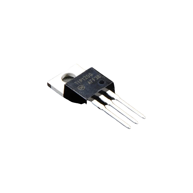
The TIP120 is an NPN Darlington transistor rated 60 V and 5 A continuous, with a current gain of at least 1000 (onsemi TIP120/D Rev. 10, p. 2). Its pins are base, collector, emitter from left to right, with the tab on the collector (p. 1). Drive the base from a GPIO through a 1 kOhm resistor (470 ohm on 3.3 V boards), put the load between the supply and the collector, and fit a flyback diode across any motor or coil; expect up to 2 V lost across it at 3 A (p. 2), so above about 1 A it needs a heat sink.
A Darlington is two transistors in one package, the first driving the second, so a few milliamps of base current switch amps at the collector. That is why the TIP120 became the standard way to let an Arduino pin run a 12 V motor, a solenoid or an LED strip: onsemi guarantees a gain of at least 1000 at 0.5 A and 3 A (datasheet, p. 2).
The cost is voltage drop. A Darlington cannot saturate as hard as a single transistor or a MOSFET: the TIP120 drops up to 2 V at 3 A and 4 V at 5 A (datasheet, p. 2), and needs up to 2.5 V between base and emitter at 3 A. At 3 A that is 6 W of heat, while the bare TO-220 sheds only 2 W in free air at 25 °C (p. 2).
So the TIP120 is comfortable at up to about 1 A without a heat sink, and works from both 5 V and 3.3 V boards, which logic-level MOSFETs such as the IRLZ44N do with far less heat. It has built-in base-emitter resistors (about 8 kOhm and 120 ohm, p. 3) that help it turn off cleanly.
TIP120 pinout
| Pin | Function | Type |
|---|---|---|
| B | Base | input |
| C | CollectorUp to 60 V | open collector |
| E | Emitter | passive |
How to wire the TIP120
Pin by pin, for the board you have.
| TIP120 | Arduino Uno | Note |
|---|---|---|
| B | D9 | Through a 1 kOhm resistor: about 3.6 mA of base current, enough for 1 A to 2 A at a gain of 1000. |
| E | GND | Also to the 12 V supply's negative. |
| C | Motor - | Motor + goes to the 12 V supply's +. Flyback diode (1N4007 or 1N5819) across the motor, cathode (stripe) to 12 V. |
- The motor runs from its own 12 V supply; join its ground to the Uno's GND at the emitter.
- Fit the flyback diode before powering a motor, solenoid or relay coil.
- Above about 1 A, bolt the TIP120 to a heat sink; the tab is the collector, so insulate it.
| TIP120 | ESP32 DevKit V1 | Note |
|---|---|---|
| B | GPIO25 (D25) | Through a 470 ohm resistor: about 4 mA from a 3.3 V pin. |
| E | GND | Also to the 12 V supply's negative. |
| C | Motor - | Motor + to the 12 V supply's +. Flyback diode across the motor, cathode to 12 V. |
- Only the base resistor touches the ESP32; the collector side carries 12 V and must never reach a GPIO.
- With a 3.3 V drive the TIP120 suits loads up to about 1 A; for more, use a logic-level MOSFET.
| TIP120 | Raspberry Pi Pico | Note |
|---|---|---|
| B | GP15 | Through a 470 ohm resistor: about 4 mA from a 3.3 V pin. |
| E | GND | Also to the 12 V supply's negative. |
| C | Motor - | Motor + to the 12 V supply's +. Flyback diode across the motor, cathode to 12 V. |
- Keep the 12 V supply away from VSYS and VBUS; share only ground with the Pico.
- With a 3.3 V drive the TIP120 suits loads up to about 1 A.
TIP120 code
Every example here compiles for its board.
// TIP120 on Arduino Uno: wiring and a free simulation at https://www.tinkered.ai/components/tip120
// TIP120 low-side switch on an Arduino Uno: base via 1 kOhm from D9, motor from 12 V to the collector,
// flyback diode across the motor. Ramps the motor speed up and down with PWM.
const int BASE_PIN = 9;

void setup() {
  Serial.begin(115200);
  pinMode(BASE_PIN, OUTPUT);
  Serial.println("TIP120 motor ramp");
}

void loop() {
  for (int duty = 0; duty <= 255; duty += 5) {
    analogWrite(BASE_PIN, duty);
    if (duty % 50 == 0) {
      Serial.print("Duty ");
      Serial.print(duty * 100 / 255);
      Serial.println(" %");
    }
    delay(40);
  }
  delay(1000);
  for (int duty = 255; duty >= 0; duty -= 5) {
    analogWrite(BASE_PIN, duty);
    delay(40);
  }
  Serial.println("Stopped");
  delay(2000);
}
// TIP120 on ESP32 DevKit V1: wiring and a free simulation at https://www.tinkered.ai/components/tip120
// TIP120 low-side switch on an ESP32 DevKit V1: base via 470 ohm from GPIO25, motor from 12 V to the collector,
// flyback diode across the motor. Ramps the motor speed up and down with PWM.
const int BASE_PIN = 25;

void setup() {
  Serial.begin(115200);
  pinMode(BASE_PIN, OUTPUT);
  analogWrite(BASE_PIN, 0);
  Serial.println("TIP120 motor ramp");
}

void loop() {
  for (int duty = 0; duty <= 255; duty += 5) {
    analogWrite(BASE_PIN, duty);
    if (duty % 50 == 0) Serial.printf("Duty %d %%\n", duty * 100 / 255);
    delay(40);
  }
  delay(1000);
  for (int duty = 255; duty >= 0; duty -= 5) {
    analogWrite(BASE_PIN, duty);
    delay(40);
  }
  Serial.println("Stopped");
  delay(2000);
}
// TIP120 on Raspberry Pi Pico: wiring and a free simulation at https://www.tinkered.ai/components/tip120
// TIP120 low-side switch on a Raspberry Pi Pico (arduino-pico): base via 470 ohm from GP15,
// motor from 12 V to the collector, flyback diode across the motor. Ramps the speed with PWM.
const int BASE_PIN = 15;

void setup() {
  Serial.begin(115200);
  pinMode(BASE_PIN, OUTPUT);
  analogWriteRange(255);
  analogWrite(BASE_PIN, 0);
  Serial.println("TIP120 motor ramp");
}

void loop() {
  for (int duty = 0; duty <= 255; duty += 5) {
    analogWrite(BASE_PIN, duty);
    if (duty % 50 == 0) {
      Serial.print("Duty ");
      Serial.print(duty * 100 / 255);
      Serial.println(" %");
    }
    delay(40);
  }
  delay(1000);
  for (int duty = 255; duty >= 0; duty -= 5) {
    analogWrite(BASE_PIN, duty);
    delay(40);
  }
  Serial.println("Stopped");
  delay(2000);
}
Before you wire it
- Put a resistor between the GPIO and the base: 1 kOhm from 5 V, 470 ohm from 3.3 V. The base-emitter junction is not a resistor, and the maximum base current is 120 mA (onsemi datasheet, p. 2).
- Fit a flyback diode across every motor, solenoid or relay coil, cathode to the positive supply.
- Join the load supply's ground, the emitter and your board's GND.
- Estimate the heat: VCE(sat) x current. It can reach 2 V at 3 A (datasheet, p. 2), so 6 W, against 2 W in free air; use a heat sink above about 1 A.
- Never switch more than 60 V or 5 A continuous (datasheet, p. 2).
- Never wire the load between the emitter and ground with the collector on the supply: as an emitter follower it loses another 2 V or so and runs hot.
- Never mount it on a grounded heat sink without an insulating pad: the tab is the collector (datasheet, p. 1).
- Never rely on the transistor alone to absorb a coil's spike; its unclamped inductive energy rating is only 50 mJ (datasheet, p. 2).
- Base current needed is load current divided by the gain, with margin: onsemi's own saturation test uses 12 mA for 3 A (datasheet, p. 2), a forced gain of 250. A 1 kOhm resistor from 5 V gives about 3.6 mA, comfortable for 1 A.
- The Darlington's base-emitter drop is about two diode drops and up to 2.5 V at 3 A (datasheet, p. 2), which is why 3.3 V boards need the smaller 470 ohm resistor.
- Internal resistors of about 8 kOhm and 120 ohm across the two base-emitter junctions (datasheet, p. 3) keep it off when the GPIO floats at boot, but a 10 kOhm pull-down from base to ground is still good practice.
- PWM works up to a few kilohertz; the TIP120 switches slowly compared with a MOSFET, so very high PWM frequencies add switching heat.
- For loads above 1 A or long run times, a logic-level MOSFET (IRLZ44N) wastes far less power than the TIP120's 1 V to 2 V drop.
Specifications
- Collector-emitter voltage (VCEO)
- 60 Vonsemi TIP120/D Rev. 10, p. 2
- Collector current
- 5 A continuous, 8 A peakonsemi TIP120/D Rev. 10, p. 2
- Base current (maximum)
- 120 mAonsemi TIP120/D Rev. 10, p. 2
- DC current gain (hFE)
- 1000 minimum at 0.5 A and at 3 A (VCE = 3 V)onsemi TIP120/D Rev. 10, p. 2
- Saturation voltage VCE(sat)
- 2 V maximum at 3 A (IB = 12 mA); 4 V maximum at 5 A (IB = 20 mA)onsemi TIP120/D Rev. 10, p. 2
- Base-emitter on voltage
- 2.5 V maximum at 3 Aonsemi TIP120/D Rev. 10, p. 2
- Power dissipation
- 2 W in free air at 25 °C; 65 W with the case held at 25 °Consemi TIP120/D Rev. 10, p. 2
- Thermal resistance
- 62.5 °C/W junction to ambient, 1.92 °C/W junction to caseonsemi TIP120/D Rev. 10, p. 2
- Pinout (TO-220)
- 1 base, 2 collector, 3 emitter; tab is collectoronsemi TIP120/D Rev. 10, p. 1
From the TIP120, TIP121, TIP122 (NPN); TIP125, TIP126, TIP127 (PNP) Plastic Medium-Power Complementary Silicon Transistors, TIP120/D Rev. 10, published by onsemi (also ST and others).
Common mistakes
No flyback diode on a motor
When the transistor turns off, the motor's inductance drives the collector far above the supply. The TIP120's 60 V rating and 50 mJ inductive energy limit (onsemi datasheet, p. 2) are easy to exceed; a 1N4007 or Schottky across the motor clamps it.
Expecting 5 A without a heat sink
The 5 A rating assumes the case is cooled. In free air the TO-220 handles 2 W at 25 °C (datasheet, p. 2), while at 3 A it can drop 2 V, three times that. Above about 1 A, add a heat sink or switch to a MOSFET.
Base straight to the GPIO
Without a resistor the base-emitter junction draws whatever the pin will give, which can damage the pin and the transistor. Always use 470 ohm to 1 kOhm.
Mixing up the pins
The TO-220 TIP120 is base, collector, emitter from the left (datasheet, p. 1), not the emitter-base-collector order of many small TO-92 transistors.
TIP120 questions
What is the TIP120 pinout?
Facing the printed side with the leads down: base on the left, collector in the middle, emitter on the right. The metal tab is connected to the collector (onsemi datasheet, p. 1).
What base resistor should I use with a TIP120?
About 1 kOhm from a 5 V Arduino pin and 470 ohm from a 3.3 V ESP32 or Pico pin, which gives roughly 3.6 to 4 mA. With a guaranteed gain of 1000 (datasheet, p. 2) that comfortably switches 1 A.
TIP120 or MOSFET for an Arduino motor?
A logic-level MOSFET such as the IRLZ44N wastes much less power, since the TIP120 drops 1 V to 2 V when on (datasheet, p. 2). The TIP120 is still fine for loads up to about 1 A and is very forgiving to drive.
Does the TIP120 work with an ESP32 or Raspberry Pi Pico?
Yes. A 3.3 V pin through 470 ohm gives about 4 mA of base current, enough for loads up to about 1 A. Keep the load's supply on the collector side only and share ground.
Why does my TIP120 get hot?
It loses VCE(sat) x current: up to 2 V at 3 A, or 6 W (datasheet, p. 2). Without a heat sink it can only shed about 2 W at 25 °C. Add a heat sink, cut the current, or use a MOSFET.
Build something with the TIP120
- Build this
PC fan speed controller
Set a 12 V fan's speed from a temperature reading.
- Build this
LED strip dimmer
Fade a single-colour 12 V LED strip from a knob.
- Build this
Solenoid door latch
Pulse a 12 V solenoid lock from a keypad code.
This page as plain Markdown, for ChatGPT, Claude or your own agent. /components/tip120.md