4 Channel Relay Module
A 5 V board with four Songle SRD-05VDC-SL-C relays, optocoupled active-low inputs and a JD-VCC jumper, for switching mains or DC loads from a microcontroller.
- Relay coil5 V, 71.4 mA, 70 ohm (0.36 W) per relay
- Coil pull-in and drop-outPulls in at 75 % of 5 V (3.75 V) at most; drops out below 10 %
- Contact rating, resistive (form C)10 A at 125 VAC; 7 A at 240 VAC; 7 A at 28 VDC
- Contact rating, inductive (form C)3 A at 120 VAC or 28 VDC
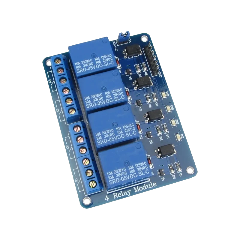
The 4 channel relay module switches four loads with Songle SRD-05VDC-SL-C relays, each drawing 71.4 mA from a 5 V coil (Songle SRD datasheet, p. 1). Its inputs are active low: IN1 to IN4 pulled LOW turn a relay on, through an optocoupler fed from VCC (Handsontec 4-channel relay guide, pp. 2, 3). Remove the VCC to JD-VCC jumper and feed JD-VCC from its own 5 V supply for true isolation; that same arrangement is what lets an ESP32 or Pico drive the board safely.
Each channel is a small chain: the input pin sinks current through a 1 kOhm resistor, the optocoupler's LED and an indicator LED, all fed from VCC; the optocoupler then turns on a transistor that powers the relay coil from JD-VCC, with a flyback diode across the coil (Handsontec guide, schematic p. 2). Writing LOW to INx switches the relay on, HIGH switches it off (p. 3).
The jumper between VCC and JD-VCC decides the isolation. With it fitted, one 5 V supply runs both the inputs and the coils, and your board's ground is shared. With it removed, VCC powers only the optocoupler LEDs from your board's 5 V, while a separate 5 V supply on JD-VCC and GND drives the coils, and the two grounds stay apart (Handsontec guide, p. 2).
The relays are rated by Songle for 10 A at 125 VAC and 7 A at 240 VAC or 28 VDC on their changeover (form C) contacts with a resistive load, and only 3 A for inductive loads such as motors (Songle SRD datasheet, p. 1). The 10 A printed on the relay top is the best case, not a figure to design to.
4 Channel Relay Module pinout
| Pin | Function | Type |
|---|---|---|
| GND | GND | power in |
| IN1 | Active low | input |
| IN2 | Active low | input |
| IN3 | Active low | input |
| IN4 | Active low | input |
| VCC | VCC5 V | power in |
| JD_VCC | JD-VCC5 V | power in |
| COM1 | Relay contact | passive |
| NO1 | Normally open | passive |
| NC1 | Normally closed | passive |
How to wire the 4 Channel Relay Module
Pin by pin, for the board you have.
| 4 Channel Relay Module | Arduino Uno | Note |
|---|---|---|
| VCC | 5V | |
| IN1 | D4 | |
| IN2 | D5 | |
| IN3 | D6 | |
| IN4 | D7 | |
| JD_VCC | Separate 5 V supply + | Jumper between VCC and JD-VCC removed. |
| GND | Separate 5 V supply - | Do not connect this GND to the Uno for full isolation. |
- For a quick bench test you may keep the jumper and wire GND to the Uno's GND, but four coils then draw about 290 mA from the Uno's 5 V.
- Mains wiring on the screw terminals is dangerous: keep it in an enclosure, away from the low-voltage side, and switch only within the relay's rating.
| 4 Channel Relay Module | ESP32 DevKit V1 | Note |
|---|---|---|
| VCC | VIN | 5 V from USB on the DevKit. VCC must be 5 V, not 3V3, for the inputs to switch reliably. |
| IN1 | GPIO26 (D26) | |
| IN2 | GPIO27 (D27) | |
| IN3 | GPIO32 (D32) | |
| IN4 | GPIO33 (D33) | |
| JD_VCC | Separate 5 V supply + | Jumper removed. |
| GND | Separate 5 V supply - | Not to the ESP32's GND. |
- A 3.3 V output works here because of the input circuit: at HIGH (3.3 V) only about 1.7 V is left across R1 and the two LEDs in series, too little to light them, and at LOW they conduct. Nothing on the IN pins rises above the ESP32's own 3.3 V.
- Keep the jumper removed and the coils on their own supply: with VCC at 5 V and the jumper on, the coil current would come through the ESP32's VIN.
| 4 Channel Relay Module | Raspberry Pi Pico | Note |
|---|---|---|
| VCC | VBUS | 5 V from USB. VCC must be 5 V for the inputs to switch reliably. |
| IN1 | GP10 | |
| IN2 | GP11 | |
| IN3 | GP12 | |
| IN4 | GP13 | |
| JD_VCC | Separate 5 V supply + | Jumper removed. |
| GND | Separate 5 V supply - | Not to the Pico's GND. |
- The Pico drives the IN pins at 3.3 V: HIGH leaves too little voltage across the input LEDs to switch them on, LOW sinks a few milliamps through the 1 kOhm resistor.
- VBUS carries 5 V only while the Pico is powered from USB; with another supply, feed VCC from a 5 V rail instead.
4 Channel Relay Module code
Every example here compiles for its board.
// 4 Channel Relay Module on Arduino Uno: wiring and a free simulation at https://www.tinkered.ai/components/relay-module-4-channel
// 4 channel relay module on an Arduino Uno: IN1..IN4 on D4..D7, active LOW
const int RELAY_PINS[4] = {4, 5, 6, 7};
const int RELAY_ON = LOW;   // the inputs are active low
const int RELAY_OFF = HIGH;

void setup() {
  Serial.begin(115200);
  for (int i = 0; i < 4; i++) {
    digitalWrite(RELAY_PINS[i], RELAY_OFF); // set HIGH before enabling the output: no click at boot
    pinMode(RELAY_PINS[i], OUTPUT);
  }
  Serial.println("Relay module ready, all off");
}

void loop() {
  for (int i = 0; i < 4; i++) {
    digitalWrite(RELAY_PINS[i], RELAY_ON);
    Serial.print("Relay "); Serial.print(i + 1); Serial.println(" ON");
    delay(1000);
    digitalWrite(RELAY_PINS[i], RELAY_OFF);
    Serial.print("Relay "); Serial.print(i + 1); Serial.println(" OFF");
    delay(500);
  }
}
// 4 Channel Relay Module on ESP32 DevKit V1: wiring and a free simulation at https://www.tinkered.ai/components/relay-module-4-channel
// 4 channel relay module on an ESP32 DevKit V1: IN1..IN4 on GPIO26, 27, 32, 33, active LOW
// VCC on VIN (5 V), JD-VCC on a separate 5 V supply, jumper removed.
const int RELAY_PINS[4] = {26, 27, 32, 33};
const int RELAY_ON = LOW;
const int RELAY_OFF = HIGH;

void setup() {
  Serial.begin(115200);
  for (int i = 0; i < 4; i++) {
    pinMode(RELAY_PINS[i], OUTPUT);
    digitalWrite(RELAY_PINS[i], RELAY_OFF); // off straight away
  }
  Serial.println("Relay module ready, all off");
}

void loop() {
  for (int i = 0; i < 4; i++) {
    digitalWrite(RELAY_PINS[i], RELAY_ON);
    Serial.printf("Relay %d ON\n", i + 1);
    delay(1000);
    digitalWrite(RELAY_PINS[i], RELAY_OFF);
    Serial.printf("Relay %d OFF\n", i + 1);
    delay(500);
  }
}
// 4 Channel Relay Module on Raspberry Pi Pico: wiring and a free simulation at https://www.tinkered.ai/components/relay-module-4-channel
// 4 channel relay module on a Raspberry Pi Pico (arduino-pico): IN1..IN4 on GP10..GP13, active LOW
// VCC on VBUS (5 V), JD-VCC on a separate 5 V supply, jumper removed.
const int RELAY_PINS[4] = {10, 11, 12, 13};
const int RELAY_ON = LOW;
const int RELAY_OFF = HIGH;

void setup() {
  Serial.begin(115200);
  for (int i = 0; i < 4; i++) {
    pinMode(RELAY_PINS[i], OUTPUT);
    digitalWrite(RELAY_PINS[i], RELAY_OFF);
  }
  Serial.println("Relay module ready, all off");
}

void loop() {
  for (int i = 0; i < 4; i++) {
    digitalWrite(RELAY_PINS[i], RELAY_ON);
    Serial.print("Relay "); Serial.print(i + 1); Serial.println(" ON");
    delay(1000);
    digitalWrite(RELAY_PINS[i], RELAY_OFF);
    Serial.print("Relay "); Serial.print(i + 1); Serial.println(" OFF");
    delay(500);
  }
}
Before you wire it
- Treat the inputs as active low: write HIGH at start-up so no relay clicks on while your board boots (Handsontec guide, p. 3).
- Power the coils from a 5 V supply that can deliver about 72 mA per relay, roughly 290 mA with all four on (Songle datasheet, p. 1).
- For isolation, remove the VCC to JD-VCC jumper, feed JD-VCC and GND from their own 5 V supply and leave your board's GND unconnected to the module (Handsontec guide, p. 2).
- On a 3.3 V board, keep VCC on 5 V (VIN or VBUS) and the jumper removed; the guide's alternative of VCC on 3.3 V leaves the optocoupler LEDs barely lit.
- Derate for motors, pumps and transformers: 3 A inductive per relay (Songle datasheet, p. 1).
- Never run mains through a bare module on a desk: use an enclosure, strain-relieved cables and a fuse.
- Never switch more than 7 A at 240 VAC or 28 VDC on the form C contacts with a resistive load (Songle datasheet, p. 1), whatever the relay top says.
- Never power the four coils from a 3.3 V pin: they need 5 V and nearly 300 mA.
- Never fit the VCC to JD-VCC jumper while a separate supply feeds JD-VCC: it ties two 5 V supplies together.
- Each input runs VCC, a 1 kOhm resistor, the optocoupler's LED and the indicator LED in series into the IN pin (Handsontec schematic, p. 2). Pulling IN low lights both; leaving it high or floating keeps them dark.
- The coil side has its own NPN transistor and a flyback diode across each coil (schematic, p. 2), so you need no extra diode on the module.
- The relay needs at least 3.75 V on the coil to pull in (75 % of 5 V, Songle datasheet p. 1); a sagging USB supply with all four relays on can leave some chattering.
- NO closes on COM when the relay is on; NC is closed when it is off. Wire lamps and pumps to NO so they stay off if your board resets.
- The 2-channel and 8-channel boards use the same per-channel circuit and jumper, with as many IN pins as relays.
Specifications
- Relay coil
- 5 V, 71.4 mA, 70 ohm (0.36 W) per relaySongle SRD datasheet (SRD-05VDC-SL-C), p. 1, coil data chart
- Coil pull-in and drop-out
- Pulls in at 75 % of 5 V (3.75 V) at most; drops out below 10 %Songle SRD datasheet, p. 1
- Contact rating, resistive (form C)
- 10 A at 125 VAC; 7 A at 240 VAC; 7 A at 28 VDCSongle SRD datasheet, p. 1, contact rating
- Contact rating, inductive (form C)
- 3 A at 120 VAC or 28 VDCSongle SRD datasheet, p. 1, contact rating
- Input logic
- Active low: relay on and LED lit when INx is LOWHandsontec 4 Channel 5V Relay Module guide, p. 3
- Input circuit
- VCC through 1 kOhm, optocoupler LED and indicator LED to INx; flyback diode across each coilHandsontec 4 Channel 5V Relay Module guide, schematic p. 2
- Isolation
- Remove the VCC to JD-VCC jumper and power JD-VCC and GND from a separate 5 V supplyHandsontec 4 Channel 5V Relay Module guide, p. 2
- 3.3 V boards
- Supported when JD-VCC has its own 5 V supply and the jumper is removedHandsontec 4 Channel 5V Relay Module guide, p. 3
- Coil current, all four on
- About 286 mA (4 x 71.4 mA) from JD-VCCSongle SRD datasheet, p. 1 (71.4 mA per coil)
From the Handson Technology 4 Channel 5V Optical Isolated Relay Module user guide, published by Songle (relays); generic module.
Common mistakes
Relays switch on at boot
The inputs are active low, so any pin that starts LOW turns its relay on. Write HIGH first (on an Uno, digitalWrite HIGH before pinMode OUTPUT), and choose pins that are not pulled low during boot.
Powering VCC from 3.3 V on an ESP32
With VCC at 3.3 V the 1 kOhm resistor and two LEDs leave almost no current for the optocoupler, so relays click unreliably; Handsontec itself suggests a smaller resistor or 5 V on VCC (guide, p. 3). Feed VCC from VIN or VBUS and drive IN at 3.3 V.
Trusting the 10 A marking for a motor
Inductive loads arc the contacts. Songle rates the changeover contacts at 3 A for inductive loads (datasheet, p. 1); a pump or compressor needs a bigger contactor or a solid-state relay.
Brown-outs with all relays on
Four coils draw about 290 mA (Songle datasheet, p. 1). From a USB-powered board with the jumper fitted, that can reset the microcontroller. Use a separate 5 V supply on JD-VCC.
Keeping the jumper while wiring a separate supply
With the jumper fitted and a second 5 V supply on JD-VCC, two supplies are tied together through VCC. Remove the jumper whenever JD-VCC has its own supply.
4 Channel Relay Module questions
Is the 4 channel relay module active high or active low?
Active low: a LOW on INx lights its LED and turns the relay on, HIGH turns it off (Handsontec guide, p. 3). Some sellers offer high-level trigger versions with a selector jumper; the common blue board with optocouplers is low-level.
Can an ESP32 or Raspberry Pi Pico control a 5 V relay module?
Yes, if VCC stays on 5 V and JD-VCC has its own 5 V supply with the jumper removed (Handsontec guide, p. 3). A 3.3 V HIGH leaves too little voltage to light the input LEDs, so the relay stays off, and a LOW sinks a few milliamps to switch it on.
What does the JD-VCC jumper do?
It joins the coil supply (JD-VCC) to the input supply (VCC). Fitted, one 5 V source runs everything. Removed, the coils run from a separate supply on JD-VCC and GND, and only light passes from your board to the relay side through the optocouplers (guide, p. 2).
How much current does the relay module draw?
Each SRD-05VDC-SL-C coil draws 71.4 mA at 5 V (Songle datasheet, p. 1), so about 290 mA with all four on, plus a few milliamps per input LED.
What can I switch with it?
Resistive loads up to 10 A at 125 VAC or 7 A at 240 VAC and 28 VDC per changeover contact, and 3 A for inductive loads (Songle datasheet, p. 1). For frequent switching of AC loads, a solid-state relay wears better.
Build something with the 4 Channel Relay Module
- Build this
Wi-Fi power strip
Switch four sockets from a phone, with timers.
- Build this
Garden irrigation controller
Open four watering valves in turn.
- Build this
Aquarium controller
Run lights, heater, filter and pump on schedules.
This page as plain Markdown, for ChatGPT, Claude or your own agent. /components/relay-module-4-channel.md