G3MB-202P SSR
A 5 V solid-state relay module built on the Omron G3MB-202P, switching AC loads of 0.1 A to 2 A at 100 to 240 VAC silently, at the zero crossing.
- Load2 A at 100 to 240 VAC rated; 75 to 264 VAC range; 0.1 A minimum load current
- Surge current30 A for one 60 Hz cycle
- Input (5 V version)4 to 6 VDC, 440 ohm input impedance (internal resistor)
- SwitchingZero cross; operate and release within half a mains cycle plus 1 ms
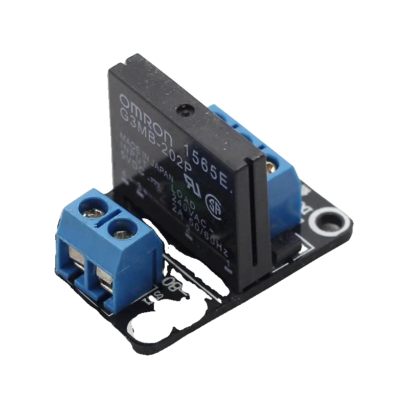
The G3MB-202P is Omron's 2 A solid-state relay: a phototriac with zero-cross switching and a built-in snubber that switches 100 to 240 VAC loads between 0.1 A and 2 A (Omron G3MB datasheet, pp. 1, 2). It switches AC only. The common module wraps it with a driver and an active-low CH1 input, powered from 4 V to 6 V on DC+ and DC- (ProtoSupplies Solid State AC Relay Module 5V x 1 page). Its input needs about 3.1 V to turn the relay fully off, so drive it from a 3.3 V board through an NPN transistor.
A solid-state relay has no moving contacts: the G3MB-202P lights an LED that triggers a phototriac, which conducts the AC load. Omron's 5 V version accepts 4 V to 6 V on its input with an internal resistor (440 ohm), switches at the zero crossing of the mains waveform, and includes a snubber (Omron datasheet, pp. 1, 2). It is silent, does not wear out, and switches within half a mains cycle plus 1 ms (p. 2).
The trade-offs are clear in the datasheet. It switches AC only, from 75 V to 264 V; it needs at least 0.1 A of load current; it leaks up to 1 mA at 100 VAC and 1.5 mA at 200 VAC when off; and it drops up to 1.6 V while on (pp. 1, 2). A tiny LED lamp can glow faintly or flicker through that leakage.
The module board adds a transistor driver, an indicator LED, a reverse-polarity diode and often a 2 A fuse on the AC side (ProtoSupplies module page). Its CH1 input is active low and draws under 1 mA; a HIGH, or no connection, turns the relay off. With DC+ at 5 V, a HIGH must reach about 3.1 V to switch it fully off, which is why a 3.3 V board drives it through a transistor.
G3MB-202P SSR pinout
| Pin | Function | Type |
|---|---|---|
| DC_PLUS | DC+4 V to 6 V (5 V typical) | power in |
| DC_MINUS | DC- | power in |
| CH1 | Active low | input |
| AC1 | AC switch75 to 264 VAC, 2 A | passive |
| AC2 | AC switch | passive |
How to wire the G3MB-202P SSR
Pin by pin, for the board you have.
| G3MB-202P SSR | Arduino Uno | Note |
|---|---|---|
| DC_PLUS | 5V | |
| DC_MINUS | GND | |
| CH1 | D7 | Direct: the Uno's 5 V HIGH switches it fully off. |
| AC1 | Mains live in | Mains side: insulated, enclosed and fused. |
| AC2 | Lamp live |
- Mains voltages kill. Keep the AC side in a closed enclosure, use rated cable and a fuse, and never work on it while plugged in.
- AC only: it will not switch a DC load off once triggered.
| G3MB-202P SSR | ESP32 DevKit V1 | Note |
|---|---|---|
| DC_PLUS | VIN | 5 V from USB. |
| DC_MINUS | GND | Also to the transistor's emitter. |
| CH1 | 2N3904 collector | NPN emitter to GND, base to GPIO26 (D26) through 1 kOhm. GPIO HIGH turns the relay on. |
| AC1 | Mains live in | |
| AC2 | Lamp live |
- Do not wire CH1 straight to the ESP32: a 3.3 V HIGH may not reach the 3.1 V the module needs to switch off, and the module pulls an open input toward its 5 V supply.
- Mains wiring belongs in a closed, fused enclosure.
| G3MB-202P SSR | Raspberry Pi Pico | Note |
|---|---|---|
| DC_PLUS | VBUS | 5 V from USB. |
| DC_MINUS | GND | Also to the transistor's emitter. |
| CH1 | 2N3904 collector | NPN emitter to GND, base to GP14 through 1 kOhm. GPIO HIGH turns the relay on. |
| AC1 | Mains live in | |
| AC2 | Lamp live |
- Keep CH1 off the Pico's pins: drive it through the transistor so no 5 V reaches a GPIO.
- Mains wiring belongs in a closed, fused enclosure.
G3MB-202P SSR code
Every example here compiles for its board.
// G3MB-202P SSR on Arduino Uno: wiring and a free simulation at https://www.tinkered.ai/components/ssr-g3mb-202p
// G3MB-202P SSR module on an Arduino Uno: CH1 on D7, active LOW. Switches a lamp every 3 s.
const int SSR_PIN = 7;

void setup() {
  Serial.begin(115200);
  digitalWrite(SSR_PIN, HIGH); // HIGH = off, set before the pin becomes an output
  pinMode(SSR_PIN, OUTPUT);
  Serial.println("SSR ready, lamp off");
}

void loop() {
  digitalWrite(SSR_PIN, LOW);  // on at the next zero crossing
  Serial.println("Lamp ON");
  delay(3000);
  digitalWrite(SSR_PIN, HIGH); // off at the next zero crossing
  Serial.println("Lamp OFF");
  delay(3000);
}
// G3MB-202P SSR on ESP32 DevKit V1: wiring and a free simulation at https://www.tinkered.ai/components/ssr-g3mb-202p
// G3MB-202P SSR module on an ESP32 DevKit V1 through a 2N3904: GPIO26 HIGH pulls CH1 low = relay ON.
const int SSR_DRIVE_PIN = 26;

void setup() {
  Serial.begin(115200);
  pinMode(SSR_DRIVE_PIN, OUTPUT);
  digitalWrite(SSR_DRIVE_PIN, LOW); // transistor off, CH1 high, lamp off
  Serial.println("SSR ready, lamp off");
}

void loop() {
  digitalWrite(SSR_DRIVE_PIN, HIGH);
  Serial.println("Lamp ON");
  delay(3000);
  digitalWrite(SSR_DRIVE_PIN, LOW);
  Serial.println("Lamp OFF");
  delay(3000);
}
// G3MB-202P SSR on Raspberry Pi Pico: wiring and a free simulation at https://www.tinkered.ai/components/ssr-g3mb-202p
// G3MB-202P SSR module on a Raspberry Pi Pico (arduino-pico) through a 2N3904: GP14 HIGH = relay ON.
const int SSR_DRIVE_PIN = 14;

void setup() {
  Serial.begin(115200);
  pinMode(SSR_DRIVE_PIN, OUTPUT);
  digitalWrite(SSR_DRIVE_PIN, LOW); // transistor off, CH1 high, lamp off
  Serial.println("SSR ready, lamp off");
}

void loop() {
  digitalWrite(SSR_DRIVE_PIN, HIGH);
  Serial.println("Lamp ON");
  delay(3000);
  digitalWrite(SSR_DRIVE_PIN, LOW);
  Serial.println("Lamp OFF");
  delay(3000);
}
Before you wire it
- Switch only AC loads between 75 VAC and 264 VAC and between 0.1 A and 2 A (Omron datasheet, pp. 1, 2).
- Share ground between DC- and your board, and keep DC+ between 4 V and 6 V (ProtoSupplies module page).
- On a 3.3 V board, drive CH1 through an NPN transistor: the module needs about 3.1 V to switch off when DC+ is 5 V.
- Allow for inrush: incandescent lamps and motors can draw many times their running current; the surge limit is 30 A for one cycle (Omron datasheet, p. 2).
- Put the mains side in a closed enclosure with a fuse, and switch the live wire, not neutral.
- Never switch DC with it: a triac only turns off when the current falls through zero.
- Never expect it to dim a lamp with PWM: zero-cross switching only turns whole half cycles on or off.
- Never treat it as an isolating switch for maintenance: it leaks up to 1.5 mA at 200 VAC when off (Omron datasheet, p. 2).
- Never run 2 A continuously in a hot, closed box without checking the derating curve: the allowed current falls with ambient temperature (datasheet, p. 2).
- The input is the LED of a phototriac with Omron's built-in 440 ohm resistor on the 5 V version (datasheet, p. 2); the module adds a transistor so the CH1 pin itself draws under 1 mA (ProtoSupplies page).
- Zero-cross switching turns the load on and off only near 0 V on the mains, which cuts interference and inrush for resistive loads, and means a command takes effect within about half a cycle plus 1 ms (datasheet, p. 2).
- The output drops up to 1.6 V RMS when on (datasheet, p. 2), about 3 W at 2 A, which warms the relay; give it airflow at full current.
- With the 2N3904 driver, the logic is inverted: GPIO HIGH turns the transistor on, pulls CH1 low and turns the relay on. At boot the GPIO floats or reads low, so the lamp stays off.
- Boards with 2, 4 or 8 SSRs share DC+ and DC- and add CH2 to CH8, each with the same input circuit.
Specifications
- Load
- 2 A at 100 to 240 VAC rated; 75 to 264 VAC range; 0.1 A minimum load currentOmron G3MB datasheet, pp. 1, 2
- Surge current
- 30 A for one 60 Hz cycleOmron G3MB datasheet, p. 2
- Input (5 V version)
- 4 to 6 VDC, 440 ohm input impedance (internal resistor)Omron G3MB datasheet, p. 2
- Switching
- Zero cross; operate and release within half a mains cycle plus 1 msOmron G3MB datasheet, pp. 1, 2
- Off-state leakage
- 1 mA at 100 VAC, 1.5 mA at 200 VACOmron G3MB datasheet, p. 2
- On-state voltage drop
- 1.6 V RMS maximumOmron G3MB datasheet, p. 2
- Isolation
- Phototriac; 2500 VAC for 1 minute between input and outputOmron G3MB datasheet, pp. 1, 2
- Module input
- CH1 active low, under 1 mA; must reach about 3.1 V to switch off with DC+ at 5 VProtoSupplies Solid State AC Relay Module 5V x 1 product page
- Module supply
- 4 V to 6 V on DC+, about 10 mA while the relay is on; reverse-polarity diodeProtoSupplies Solid State AC Relay Module 5V x 1 product page
From the Omron G3MB Solid State Relay datasheet, published by Omron (SSR); generic module.
Common mistakes
Trying to switch a 12 V DC load
The G3MB-202P is a phototriac (Omron datasheet, p. 1). Once it conducts DC it stays on until the current stops. For DC loads use a MOSFET or a mechanical relay.
LED bulb glows when off
When off, the SSR still leaks up to 1 mA at 100 VAC and 1.5 mA at 200 VAC (datasheet, p. 2), and its minimum load is 0.1 A. A small LED lamp can glow or flicker; add a bleeder load or use a mechanical relay.
Relay never turns off on an ESP32
With DC+ at 5 V, CH1 needs about 3.1 V to switch the relay fully off (ProtoSupplies page). A 3.3 V output may sit right at that edge. Drive CH1 through an NPN transistor instead.
Using it for a motor or heater above 2 A
The rating is 2 A (datasheet, p. 1) and shrinks with heat. A 1500 W heater draws far more; use a larger SSR with a heat sink or a contactor.
G3MB-202P SSR questions
Solid-state relay or mechanical relay?
The G3MB-202P is silent, switches at the zero crossing and has no contacts to wear, but it switches AC only, up to 2 A, leaks a little when off and needs at least 0.1 A of load (Omron datasheet, pp. 1, 2). A mechanical relay switches AC or DC and higher currents, with a click and finite contact life.
Can the G3MB-202P switch DC?
No. It is a phototriac, which stays on until the load current passes through zero, and that never happens with DC. Use a MOSFET or a mechanical relay for DC loads.
Is the SSR module active high or active low?
The common module is active low: CH1 LOW turns it on, HIGH or no connection turns it off (ProtoSupplies module page). Some sellers offer high-level versions, so check the board's markings.
Can I dim a lamp with this SSR?
No. Zero-cross switching only turns the output on or off at the start of a half cycle, so PWM gives flicker, not smooth dimming. Dimming needs a random-phase triac driver synchronised to the mains.
Does it work with a 3.3 V board?
Only marginally when wired directly: with DC+ at 5 V the input needs about 3.1 V to turn the relay off (ProtoSupplies page). Use an NPN transistor between the GPIO and CH1, as in the ESP32 and Pico wiring here.
Build something with the G3MB-202P SSR
- Build this
Terrarium heat lamp controller
Hold a temperature with a heat lamp switched silently.
- Build this
Smart lamp
Switch a table lamp from a phone.
- Build this
Christmas light sequencer
Run several light strings in patterns.
This page as plain Markdown, for ChatGPT, Claude or your own agent. /components/ssr-g3mb-202p.md