S9V11F5
A thumbnail-sized Pololu buck-boost regulator that holds 5 V from any input between 2 V and 16 V, ideal for running a 5 V board from AA cells or one lithium cell.
- Input voltage3 V to 16 V to start; runs down to 2 V once started
- Output5 V, 3 % accuracy
- Output currentUp to 1.5 A with VIN at or above VOUT; about 700 mA during start-up
- Efficiency85 % to 95 % typical
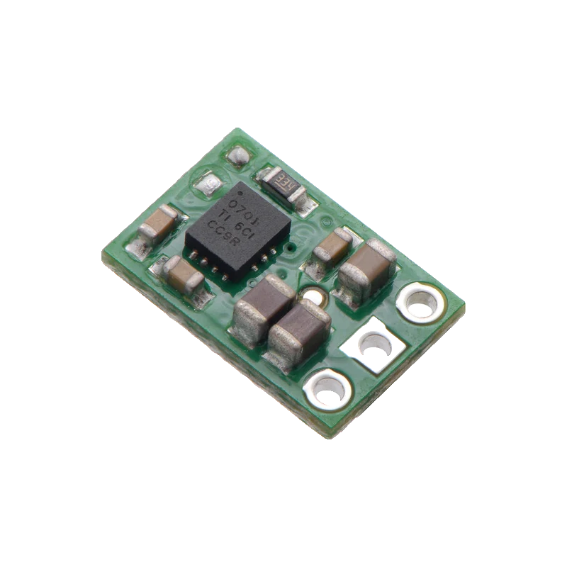
The S9V11F5 is Pololu's 5 V buck-boost regulator: it starts from 3 V, keeps running down to 2 V and accepts up to 16 V, raising or lowering the input to a steady 5 V at 85 % to 95 % typical efficiency (Pololu #2836 product page). It supplies up to 1.5 A when the input is at or above 5 V, but only about 700 mA during start-up (#2836). Three pins, VIN, GND and VOUT, plus an EN pin for sleep or a low-battery cut-off.
A buck-boost converter solves the battery problem: three AA cells start at about 4.8 V and fall to 3 V, and a lithium cell runs 4.2 V to 3 V, both straddling the 5 V a board wants. The S9V11F5 steps up or down as needed and keeps the output at 5 V within 3 % (Pololu #2836), so the board sees the same voltage from a fresh pack to a nearly empty one.
Its available current depends on the input: about 1.5 A when the input is at or above the output, less when it has to boost from a low cell, and only about 700 mA until the output first reaches 5 V (#2836). Quiescent current stays under 0.2 mA over most of the range, and soft-start ramps the output to limit inrush.
EN is pulled up to VIN through 100 kOhm and puts the regulator to sleep below 0.7 V, waking above 0.8 V (#2836). That tight threshold lets a resistor divider from VIN act as a precise low-battery cut-off, protecting lithium cells from over-discharge. There is no reverse-polarity protection on the board.
S9V11F5 pinout
| Pin | Function | Type |
|---|---|---|
| EN | EnableSleep below 0.7 V, run above 0.8 V | input |
| VIN | VIN2 V to 16 V (3 V to start) | power in |
| GND | GND | power in |
| VOUT | VOUT5 V, up to 1.5 A | power out |
How to wire the S9V11F5
Pin by pin, for the board you have.
| S9V11F5 | Arduino Uno | Note |
|---|---|---|
| VIN | Battery + (3 x AA) | Also to A0 directly: at most 4.8 V from three AA cells, inside the 5 V ADC range. |
| GND | Battery - and GND | |
| VOUT | 5V | Unplug the Uno's USB while the regulator feeds its 5V pin. |
| EN | not connected | Pulled up to VIN: always on. |
- There is no reverse-voltage protection: a battery wired backwards destroys the regulator (#2836).
- With a battery pack above 5 V, divide it before A0.
| S9V11F5 | ESP32 DevKit V1 | Note |
|---|---|---|
| VIN | Battery + (3 x AA or one Li-ion cell) | Also to GPIO34 through a 100 kOhm / 100 kOhm divider. |
| GND | Battery - and GND | |
| VOUT | VIN | |
| EN | not connected |
- Never connect VOUT (5 V) to the 3V3 pin or a GPIO.
- An ESP32's Wi-Fi peaks need current: from a single cell the regulator must boost, so its available current is lower than the 1.5 A figure.
| S9V11F5 | Raspberry Pi Pico | Note |
|---|---|---|
| VIN | Battery + (3 x AA or one Li-ion cell) | Also to GP26 through a 100 kOhm / 100 kOhm divider. |
| GND | Battery - and GND | |
| VOUT | VSYS | Through a Schottky diode (anode at VOUT) if USB may also be connected (Raspberry Pi Pico datasheet, p. 22). |
| EN | not connected |
- The Pico runs on VSYS from 1.8 V to 5.5 V (Pico datasheet, p. 9); the regulator mainly helps when other 5 V parts share the supply.
S9V11F5 code
Every example here compiles for its board.
// S9V11F5 on Arduino Uno: wiring and a free simulation at https://www.tinkered.ai/components/s9v11f5
// S9V11F5 feeding an Arduino Uno's 5V pin from 3 x AA; the pack is read on A0 directly.
const int BAT_PIN = A0;
const float PACK_EMPTY = 3.0; // three AA cells at about 1.0 V each

void setup() {
  Serial.begin(115200);
  Serial.println("S9V11F5 battery monitor");
}

void loop() {
  float vbat = analogRead(BAT_PIN) * 5.0 / 1023.0; // reference is the regulated 5 V
  Serial.print("Battery: ");
  Serial.print(vbat, 2);
  Serial.println(vbat < PACK_EMPTY ? " V  replace batteries" : " V");
  delay(2000);
}
// S9V11F5 on ESP32 DevKit V1: wiring and a free simulation at https://www.tinkered.ai/components/s9v11f5
// S9V11F5 feeding an ESP32 DevKit V1 on VIN; battery read on GPIO34 through a 100k/100k divider.
const int BAT_PIN = 34;
const float PACK_EMPTY = 3.0;

void setup() {
  Serial.begin(115200);
  Serial.println("S9V11F5 battery monitor");
}

void loop() {
  float vbat = analogReadMilliVolts(BAT_PIN) * 2.0 / 1000.0; // undo the 1:2 divider
  Serial.printf("Battery: %.2f V%s\n", vbat, vbat < PACK_EMPTY ? "  replace or recharge" : "");
  delay(2000);
}
// S9V11F5 on Raspberry Pi Pico: wiring and a free simulation at https://www.tinkered.ai/components/s9v11f5
// S9V11F5 feeding a Raspberry Pi Pico on VSYS; battery on GP26 through a 100k/100k divider.
const int BAT_PIN = 26;
const float PACK_EMPTY = 3.0;

void setup() {
  Serial.begin(115200);
  analogReadResolution(12); // 0..4095 over 0..3.3 V
  Serial.println("S9V11F5 battery monitor");
}

void loop() {
  float vbat = analogRead(BAT_PIN) * 3.3 / 4095.0 * 2.0;
  Serial.print("Battery: ");
  Serial.print(vbat, 2);
  Serial.println(vbat < PACK_EMPTY ? " V  replace or recharge" : " V");
  delay(2000);
}
Before you wire it
- Keep VIN at or below 16 V and start it from at least 3 V (Pololu #2836).
- Check polarity before connecting: the board has no reverse-voltage protection (#2836).
- Expect only about 700 mA until the output reaches 5 V (#2836); large start-up loads may need to be switched on afterwards.
- For lithium cells, use EN with a divider from VIN as a low-voltage cut-off (sleep below 0.7 V on EN), or use protected cells.
- Never exceed 16 V at the input; Pololu warns that higher voltages, including LC spikes from long leads, can destroy it (#2836).
- Never connect VOUT to a 3.3 V pin.
- Never count on 1.5 A when boosting from a low cell: the maximum current falls as the input drops below 5 V (#2836).
- The regulator raises or lowers the input as needed, so a pack that falls from above 5 V to below it keeps the output at 5 V throughout (#2836).
- EN's 100 kOhm pull-up draws about 10 µA per volt of VIN while asleep, about 30 µA at 3 V (#2836).
- A divider from VIN to EN sets a cut-off: EN = VIN x R2/(R1 + R2), and the regulator sleeps when that falls below 0.7 V.
- Long battery leads plus the board's ceramic capacitors can ring above the input voltage when power is connected (Pololu #2836 warns of LC spikes); an electrolytic capacitor across VIN and GND at the board damps them.
- Quiescent current under 0.2 mA (#2836) makes it suitable for always-on battery projects.
Specifications
- Input voltage
- 3 V to 16 V to start; runs down to 2 V once startedPololu S9V11F5 (#2836) product page
- Output
- 5 V, 3 % accuracyPololu S9V11F5 (#2836) product page
- Output current
- Up to 1.5 A with VIN at or above VOUT; about 700 mA during start-upPololu S9V11F5 (#2836) product page
- Efficiency
- 85 % to 95 % typicalPololu S9V11F5 (#2836) product page
- Quiescent current
- Under 0.2 mA over most of the rangePololu S9V11F5 (#2836) product page
- Enable
- Sleep below 0.7 V, run above 0.8 V; 100 kOhm pull-up to VIN (about 10 µA per volt in sleep)Pololu S9V11F5 (#2836) product page
- Protection
- Short-circuit and over-temperature; no reverse-voltage protectionPololu S9V11F5 (#2836) product page
- Size
- 0.30 in x 0.45 in x 0.17 inPololu S9V11F5 (#2836) product page
From the Pololu 5V Step-Up/Step-Down Voltage Regulator S9V11F5 product page, published by Pololu.
Common mistakes
Reversed battery
The S9V11F5 has no reverse-voltage protection (#2836). One wrong connection kills it; add a reverse-protection module or a keyed connector.
Board resets at power-up
Start-up current is limited to about 700 mA until the output reaches 5 V (#2836). A load that draws more at switch-on, such as a servo or a large capacitor bank, can stall the start.
Expecting full current from one cell
Boosting 3.7 V to 5 V draws more input current than output current, and Pololu's maximum-current graph falls with input voltage (#2836). Budget well under 1.5 A from a single lithium cell.
S9V11F5 questions
Can the S9V11F5 run an Arduino from AA batteries?
Yes: three or four AA cells stay within its 2 V to 16 V range as they discharge, and it holds 5 V throughout (Pololu #2836). Feed VOUT to the Uno's 5V pin with USB unplugged.
What is the difference between step-up/step-down and a boost converter?
A boost converter such as the MT3608 only raises voltage, so its output follows the input once the input exceeds the set point. A buck-boost like the S9V11F5 also steps down, so a 6 V pack still gives exactly 5 V.
How do I add a low-battery cut-off?
Use a resistor divider from VIN to EN: the regulator sleeps when EN falls below 0.7 V and wakes above 0.8 V (#2836), so choose the ratio for the cell voltage where you want to stop.
How much current can it supply?
Up to 1.5 A with the input at or above 5 V, less when boosting from a lower input, and about 700 mA during start-up (#2836).
Build something with the S9V11F5
- Build this
AA-powered sensor logger
Run an Arduino from three AA cells for weeks.
- Build this
Portable ESP32 display
Battery-powered ESP32 clock with a low-battery warning.
- Build this
Handheld Pico gadget
A Pico project that runs from AAA cells.
This page as plain Markdown, for ChatGPT, Claude or your own agent. /components/s9v11f5.md