MCP2515 CAN
A CAN bus interface module pairing Microchip's MCP2515 SPI CAN controller with a TJA1050 transceiver, for cars, robots and industrial networks.
- CAN controllerCAN 2.0B, up to 1 Mb/s, standard and extended frames, 0 to 8 data bytes
- Buffers and filters3 transmit buffers, 2 receive buffers, 6 × 29-bit filters, 2 × 29-bit masks
- SPIUp to 10 MHz, modes 0,0 and 1,1
- MCP2515 supply2.7 V to 5.5 V, 5 mA active typical
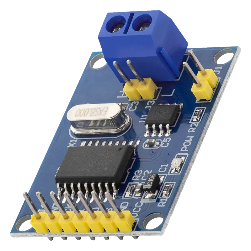
The MCP2515 module connects a microcontroller to a CAN bus: Microchip's MCP2515 implements CAN 2.0B at up to 1 Mb/s behind a 10 MHz SPI port (Microchip DS20001801J, p. 1), and a TJA1050 transceiver drives the CANH and CANL wires from a 4.75 V to 5.25 V supply (Philips TJA1050 specification, p. 2). Because the transceiver needs 5 V and the MCP2515's SPI inputs then need 0.7 × VDD (3.5 V) (DS20001801J, p. 74), the module wires straight to an Uno but needs a level shifter on an ESP32 or a Pico. The autowp-mcp2515 library sends and receives frames.
CAN is the two-wire differential bus inside cars, e-bikes, 3D printers and industrial machines. The MCP2515 handles the protocol: it frames and checks messages, filters what to accept with six 29-bit filters and two masks, and buffers three outgoing and two incoming frames (Microchip DS20001801J, p. 1). The TJA1050 turns its logic signals into the CANH/CANL differential pair, rated for up to 1 Mbaud and at least 110 nodes on one bus (Philips TJA1050 specification, p. 2).
The common blue module has a 7-pin header printed INT, SCK, SI, SO, CS, GND and VCC, a screw terminal for H and L, a crystal for the MCP2515 (usually 8 MHz, read its marking) and a jumper that adds a 120 Ω termination resistor. Both chips run from the one VCC pin, and the TJA1050 needs 4.75 V to 5.25 V, so VCC is 5 V in practice.
With VCC at 5 V, the MCP2515's SPI inputs need 3.5 V to read a high and its SO output swings to about 5 V (DS20001801J, p. 74). A 5 V Uno connects directly. On an ESP32 or a Pico, put a level shifter on SCK, SI, CS and SO and slow the SPI clock to suit it. The ESP32 also has a built-in CAN controller (TWAI) that only needs a 3.3 V transceiver, a simpler route for ESP32 designs.
MCP2515 CAN pinout
| Pin | Function | Type |
|---|---|---|
| INT | Interrupt (active low)VCC level | output |
| SCK | SPI SCKHigh from 0.7 × VCC | input |
| SI | SPI MOSIHigh from 0.7 × VCC | input |
| SO | SPI MISOVCC level | output |
| CS | SPI CS (active low)High from 0.7 × VCC | input |
| GND | Ground | power in |
| VCC | Supply5 V (TJA1050 needs 4.75 V to 5.25 V) | power in |
| H | CANH | bidirectional |
| L | CANL | bidirectional |
How to wire the MCP2515 CAN
Pin by pin, for the board you have.
| MCP2515 CAN | Arduino Uno | Note |
|---|---|---|
| VCC | 5V | |
| GND | GND | |
| CS | D10 | |
| SI | D11 | |
| SO | D12 | |
| SCK | D13 | |
| INT | D2 | |
| H / L | CANH / CANL of the bus | Fit the 120 Ω jumper only if this module is at one end of the bus. |
| MCP2515 CAN | ESP32 DevKit V1 | Note |
|---|---|---|
| VCC | VIN (5 V) and the level shifter's HV | |
| GND | GND | |
| CS | GPIO5 (D5) through a 4-channel BSS138 level shifter (LV = 3V3) | |
| SI | GPIO23 (D23) through the level shifter | |
| SO | GPIO19 (D19) through the level shifter | |
| SCK | GPIO18 (D18) through the level shifter | |
| INT | Not connected (the sketch polls) | |
| H / L | CANH / CANL of the bus | 120 Ω jumper only at the ends of the bus. |
- SO swings to 5 V and the MCP2515 needs 3.5 V for a high at 5 V (DS20001801J, p. 74): never wire the SPI lines straight to the ESP32.
- The sketch runs SPI at 1 MHz, a speed BSS138 shifters pass reliably.
| MCP2515 CAN | Raspberry Pi Pico | Note |
|---|---|---|
| VCC | VBUS (5 V from USB) and the level shifter's HV | |
| GND | GND | |
| CS | GP17 through a 4-channel BSS138 level shifter (LV = 3V3(OUT)) | |
| SI | GP19 through the level shifter | |
| SO | GP16 through the level shifter | |
| SCK | GP18 through the level shifter | |
| INT | Not connected (the sketch polls) | |
| H / L | CANH / CANL of the bus | 120 Ω jumper only at the ends of the bus. |
- Never connect SO directly to a Pico pin: it drives about 5 V when the module runs from 5 V.
MCP2515 CAN code
Every example here compiles for its board.
// MCP2515 CAN on Arduino Uno: wiring and a free simulation at https://www.tinkered.ai/components/mcp2515-can
// MCP2515 CAN module on an Arduino Uno: CS D10, SPI D11/D12/D13. 500 kbit/s, 8 MHz crystal.
// Sends a frame with ID 0x123 every second and prints every frame received.
#include <SPI.h>
#include <mcp2515.h>

MCP2515 mcp2515(10); // CS pin
struct can_frame rx;
unsigned long lastSend = 0;
uint8_t counter = 0;

void setup() {
  Serial.begin(115200);
  mcp2515.reset();
  mcp2515.setBitrate(CAN_500KBPS, MCP_8MHZ); // use MCP_16MHZ if the crystal reads 16.000
  mcp2515.setNormalMode();
  Serial.println(F("CAN ready at 500 kbit/s"));
}

void loop() {
  if (millis() - lastSend >= 1000) {
    lastSend = millis();
    struct can_frame tx;
    tx.can_id = 0x123;
    tx.can_dlc = 2;
    tx.data[0] = counter++;
    tx.data[1] = 0xAB;
    bool ok = mcp2515.sendMessage(&tx) == MCP2515::ERROR_OK;
    Serial.println(ok ? F("Sent 0x123") : F("Send failed (no other node acknowledging?)"));
  }
  if (mcp2515.readMessage(&rx) == MCP2515::ERROR_OK) {
    Serial.print(F("Received ID 0x"));
    Serial.print(rx.can_id, HEX);
    Serial.print(F(" data:"));
    for (uint8_t i = 0; i < rx.can_dlc; i++) {
      Serial.print(' ');
      Serial.print(rx.data[i], HEX);
    }
    Serial.println();
  }
}
// MCP2515 CAN on ESP32 DevKit V1: wiring and a free simulation at https://www.tinkered.ai/components/mcp2515-can
// MCP2515 CAN module on an ESP32 DevKit V1 through a BSS138 level shifter: CS GPIO5, VSPI 18/19/23. 500 kbit/s, 8 MHz crystal.
// Sends a frame with ID 0x123 every second and prints every frame received.
#include <SPI.h>
#include <mcp2515.h>

MCP2515 mcp2515(5, 1000000); // CS pin, SPI at 1 MHz for the level shifter
struct can_frame rx;
unsigned long lastSend = 0;
uint8_t counter = 0;

void setup() {
  Serial.begin(115200);
  mcp2515.reset();
  mcp2515.setBitrate(CAN_500KBPS, MCP_8MHZ);
  mcp2515.setNormalMode();
  Serial.println("CAN ready at 500 kbit/s");
}

void loop() {
  if (millis() - lastSend >= 1000) {
    lastSend = millis();
    struct can_frame tx;
    tx.can_id = 0x123;
    tx.can_dlc = 2;
    tx.data[0] = counter++;
    tx.data[1] = 0xAB;
    bool ok = mcp2515.sendMessage(&tx) == MCP2515::ERROR_OK;
    Serial.println(ok ? "Sent 0x123" : "Send failed (no other node acknowledging?)");
  }
  if (mcp2515.readMessage(&rx) == MCP2515::ERROR_OK) {
    Serial.printf("Received ID 0x%lX data:", (unsigned long)rx.can_id);
    for (uint8_t i = 0; i < rx.can_dlc; i++) Serial.printf(" %02X", rx.data[i]);
    Serial.println();
  }
}
// MCP2515 CAN on Raspberry Pi Pico: wiring and a free simulation at https://www.tinkered.ai/components/mcp2515-can
// MCP2515 CAN module on a Raspberry Pi Pico (arduino-pico) through a BSS138 level shifter: CS GP17, SPI0 GP16/18/19. 500 kbit/s, 8 MHz crystal.
// Sends a frame with ID 0x123 every second and prints every frame received.
#include <SPI.h>
#include <mcp2515.h>

MCP2515 mcp2515(17, 1000000); // CS pin, SPI at 1 MHz for the level shifter
struct can_frame rx;
unsigned long lastSend = 0;
uint8_t counter = 0;

void setup() {
  Serial.begin(115200);
  mcp2515.reset();
  mcp2515.setBitrate(CAN_500KBPS, MCP_8MHZ);
  mcp2515.setNormalMode();
  Serial.println("CAN ready at 500 kbit/s");
}

void loop() {
  if (millis() - lastSend >= 1000) {
    lastSend = millis();
    struct can_frame tx;
    tx.can_id = 0x123;
    tx.can_dlc = 2;
    tx.data[0] = counter++;
    tx.data[1] = 0xAB;
    bool ok = mcp2515.sendMessage(&tx) == MCP2515::ERROR_OK;
    Serial.println(ok ? "Sent 0x123" : "Send failed (no other node acknowledging?)");
  }
  if (mcp2515.readMessage(&rx) == MCP2515::ERROR_OK) {
    Serial.print("Received ID 0x");
    Serial.print(rx.can_id, HEX);
    Serial.print(" data:");
    for (uint8_t i = 0; i < rx.can_dlc; i++) {
      Serial.print(' ');
      Serial.print(rx.data[i], HEX);
    }
    Serial.println();
  }
}
Before you wire it
- Run VCC at 5 V: the TJA1050 needs 4.75 V to 5.25 V (Philips TJA1050 specification, p. 2).
- Match the library's clock setting to the crystal printed on the module (8.000 or 16.000 MHz) and use the same bit rate on every node.
- Terminate the bus with 120 Ω at its two ends only, using the module's jumper where it sits at an end.
- Level-shift SCK, SI, CS and SO on 3.3 V boards, and share ground with the bus's other nodes.
- Never connect the module's SO to an ESP32 or Pico pin directly when VCC is 5 V.
- Never power the module from 3.3 V and expect the TJA1050 to meet its specification.
- Never test with a single node: a CAN frame needs an acknowledgement from another node, so transmissions fail alone.
- With VCC at 5 V the MCP2515 needs 0.7 × 5 V = 3.5 V on SCK, CS and SI (DS20001801J, p. 74), above a 3.3 V board's output, which is why the shifter is needed in both directions.
- A BSS138 four-channel shifter passes SPI reliably at around 1 MHz; the autowp library takes the SPI clock as its second constructor argument.
- INT goes low when a frame arrives; on a 5 V board wire it to an interrupt pin to avoid polling, on a 3.3 V board shift it down first or poll as these sketches do.
- For an ESP32-only design, its built-in TWAI controller with a 3.3 V transceiver such as the SN65HVD230 avoids both the MCP2515 and level shifting.
- Car OBD-II ports usually run CAN at 500 kbit/s on pins 6 (CANH) and 14 (CANL); listen-only mode avoids disturbing the vehicle while you experiment.
Specifications
- CAN controller
- CAN 2.0B, up to 1 Mb/s, standard and extended frames, 0 to 8 data bytesMicrochip MCP2515 DS20001801J, p. 1
- Buffers and filters
- 3 transmit buffers, 2 receive buffers, 6 × 29-bit filters, 2 × 29-bit masksMicrochip MCP2515 DS20001801J, p. 1
- SPI
- Up to 10 MHz, modes 0,0 and 1,1Microchip MCP2515 DS20001801J, p. 1
- MCP2515 supply
- 2.7 V to 5.5 V, 5 mA active typicalMicrochip MCP2515 DS20001801J, p. 1
- MCP2515 logic levels
- SCK, CS, SI high from 0.7 × VDD; SO high at VDD - 0.5 V or moreMicrochip MCP2515 DS20001801J, Table 13-1, p. 74
- Transceiver supply (TJA1050)
- 4.75 V to 5.25 VPhilips TJA1050 High speed CAN transceiver, preliminary specification 1999 Sep 27, p. 2
- Bus
- Up to 1 Mbaud, at least 110 nodes; CANH and CANL withstand -27 V to +40 VPhilips TJA1050 specification, p. 2
From the Microchip MCP2515 Stand-Alone CAN Controller with SPI Interface, DS20001801J, published by Microchip Technology (MCP2515), NXP (TJA1050).
Common mistakes
Wrong crystal setting
Most of these modules carry an 8 MHz crystal, but code for 16 MHz shields uses MCP_16MHZ. The bit rate then comes out wrong by a factor of two and nothing is received. Read the crystal's marking and set MCP_8MHZ or MCP_16MHZ.
Testing with one node
CAN requires another node to acknowledge each frame. With only one module on the bus, sendMessage() reports errors forever. Use two modules, or a known working device on the bus.
No termination, or too much
A CAN bus needs 120 Ω at each end: about 60 Ω measured between CANH and CANL with power off. Fit the module's jumper only on the two end nodes.
Wiring a 5 V module straight to an ESP32
SO drives about 5 V back to the microcontroller and the MCP2515 needs 3.5 V highs on its inputs (DS20001801J, p. 74). Use a level shifter, or use the ESP32's own CAN controller with a 3.3 V transceiver.
MCP2515 CAN questions
Does the MCP2515 module work with an ESP32?
Yes, with a level shifter on SCK, SI, CS and SO, because the module runs at 5 V for its TJA1050 transceiver (Philips TJA1050 specification, p. 2). Many ESP32 projects skip the module and use the chip's built-in TWAI controller with a 3.3 V transceiver instead.
8 MHz or 16 MHz crystal?
Check the silver crystal on the board: most blue MCP2515 modules use 8 MHz, some shields 16 MHz. Pass the matching value (MCP_8MHZ or MCP_16MHZ) to setBitrate(), or the bit rate will be wrong.
What bit rate can the MCP2515 reach?
Up to 1 Mb/s for CAN 2.0B (Microchip DS20001801J, p. 1), which the TJA1050 also supports (TJA1050 specification, p. 2). Cars commonly use 500 kbit/s on the OBD-II port.
Which library should I use?
autowp-mcp2515 (arduino-mcp2515) is simple and handles bit rates, filters and modes. MCP_CAN by Cory Fowler is the other common choice and appears in many older tutorials.
Do I need the 120 Ω jumper?
Only on the two nodes at the physical ends of the bus. For a two-module bench test, fit it on both; in a car the bus is already terminated, so leave it off.
Build something with the MCP2515 CAN
- Build this
OBD-II data logger
Read engine RPM and speed from a car's CAN bus.
- Build this
Two-node CAN demo
A button on one board lights an LED on another over CAN.
This page as plain Markdown, for ChatGPT, Claude or your own agent. /components/mcp2515-can.md