LCD 20x4 (I2C)
A 20x4 character LCD on an HD44780-compatible controller with a PCF8574 I2C backpack: 80 characters of text on two signal wires.
- Format20 characters x 4 lines, 5x8 dot characters
- Supply (logic)4.5 V to 5.5 V, 5.0 V typical; 4.0 mA max logic current
- LCD drive voltage4.4 V min, 4.7 V typical, 5.0 V max (VDD to V0)
- Display RAM80 characters (80 x 8 bits); lines at 00h to 27h and 40h to 67h
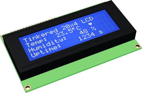
The LCD 2004 I2C is a 20 character by 4 line HD44780-compatible display with a PCF8574 I2C backpack, so it needs only VCC, GND, SDA and SCL. Power it from 5 V (the 2004A module is rated 4.5 V to 5.5 V, C2004A datasheet, p. 1) and address it at 0x27, or 0x3F on a PCF8574A backpack (TI PCF8574 and PCF8574A datasheets, p. 14). In code, create it with LiquidCrystal_I2C lcd(0x27, 20, 4), call lcd.backlight(), and turn the contrast trimpot on the back until characters appear.
The LCD 2004 shows four lines of twenty characters, 80 in all, on a 5x8 dot matrix per character, using an HD44780-compatible controller. The HD44780 has exactly 80 characters of display RAM (Hitachi HD44780U datasheet, p. 1), so the 20x4 panel uses all of it: the controller's two 40-character lines are each split across two rows, which is why text that runs past the end of row 0 continues on row 2. Eight custom 5x8 characters can be defined in its CGRAM (p. 13).
On the back sits a backpack built around a PCF8574 I2C I/O expander, which drives the LCD's controller in 4-bit mode and switches the backlight through a transistor. That cuts the wiring to four connections: VCC, GND, SDA and SCL. The PCF8574 answers at 0x20 to 0x27 depending on its A0 to A2 pins and the PCF8574A at 0x38 to 0x3F (TI PCF8574 and PCF8574A datasheets, p. 14); with the address pads left open the usual backpacks answer at 0x27 or 0x3F. The PCF8574 is a 100 kHz I2C device (TI PCF8574 datasheet, p. 5).
The 2004A module is a 5 V part: its logic supply is 4.5 V to 5.5 V and its LCD drive voltage 4.4 V to 5.0 V, 4.7 V typical (C2004A datasheet, p. 1). On 3.3 V the characters are faint or invisible, so power it from 5 V even when a 3.3 V board drives the bus. The board measures 98.0 x 60.0 mm with a 76.0 x 25.2 mm viewing area (p. 1), and a trimpot on the backpack sets the contrast.
LCD 20x4 (I2C) pinout
| Pin | Function | Type |
|---|---|---|
| GND | GND | power in |
| VCC | VCC (5V)4.5–5 V | power in |
| SDA | I2C SDA | bidirectional |
| SCL | I2C SCL | bidirectional |
How to wire the LCD 20x4 (I2C)
Pin by pin, for the board you have.
| LCD 20x4 (I2C) | Arduino Uno | Note |
|---|---|---|
| GND | GND | |
| VCC | 5V | |
| SDA | SDA | |
| SCL | SCL |
| LCD 20x4 (I2C) | ESP32 DevKit V1 | Note |
|---|---|---|
| GND | GND | |
| VCC | VIN | |
| SDA | GPIO21 (D21) | through a level shifter (a BSS138 board): the backpack pulls SDA up to its 5 V |
| SCL | GPIO22 (D22) | through a level shifter (a BSS138 board): the backpack pulls SCL up to its 5 V |
- VCC is on VIN, which gives about 5 V only while the board is powered from USB.
- The backpack runs on 5 V: its PCF8574 reads a high from 0.7 × VCC (3.5 V), above a 3.3 V pin, and its pull-ups would put 5 V on the board's SDA and SCL. Put a bidirectional level shifter on both lines, as the rows say.
| LCD 20x4 (I2C) | Raspberry Pi Pico | Note |
|---|---|---|
| GND | GND | |
| VCC | VBUS | |
| SDA | GP4 | through a level shifter (a BSS138 board): the backpack pulls SDA up to its 5 V |
| SCL | GP5 | through a level shifter (a BSS138 board): the backpack pulls SCL up to its 5 V |
- VCC is on VBUS, which gives about 5 V only while the board is powered from USB.
- The backpack runs on 5 V: its PCF8574 reads a high from 0.7 × VCC (3.5 V), above a 3.3 V pin, and its pull-ups would put 5 V on the board's SDA and SCL. Put a bidirectional level shifter on both lines, as the rows say.
LCD 20x4 (I2C) code
Every example here compiles for its board.
// LCD 20x4 (I2C) on Arduino Uno: wiring and a free simulation at https://www.tinkered.ai/components/lcd-2004-i2c
#include <Wire.h>
#include <LiquidCrystal_I2C.h>

LiquidCrystal_I2C lcd(0x27, 20, 4);   // address, columns, rows

byte degree[8] = { 0b01100, 0b10010, 0b10010, 0b01100, 0, 0, 0, 0 };

void setup() {
  Wire.begin();
  lcd.init();             // the library's entry point: starts Wire and the 20x4 display
  lcd.backlight();               // the backlight stays off until this
  lcd.createChar(0, degree);
  lcd.setCursor(0, 0); lcd.print("Weather station");
  lcd.setCursor(0, 1); lcd.print("Temp:");
  lcd.setCursor(0, 2); lcd.print("Humidity:");
  lcd.setCursor(0, 3); lcd.print("Uptime:");
}

void loop() {
  lcd.setCursor(10, 1); lcd.print("23.5"); lcd.write(0); lcd.print("C ");
  lcd.setCursor(10, 2); lcd.print("48 %  ");
  lcd.setCursor(10, 3); lcd.print(millis() / 1000); lcd.print(" s   ");
  delay(1000);
}
// LCD 20x4 (I2C) on ESP32 DevKit V1: wiring and a free simulation at https://www.tinkered.ai/components/lcd-2004-i2c
#include <Wire.h>
#include <LiquidCrystal_I2C.h>

LiquidCrystal_I2C lcd(0x27, 20, 4);   // address, columns, rows

byte degree[8] = { 0b01100, 0b10010, 0b10010, 0b01100, 0, 0, 0, 0 };

void setup() {
  Wire.begin();
  lcd.init();             // the library's entry point: starts Wire and the 20x4 display
  lcd.backlight();               // the backlight stays off until this
  lcd.createChar(0, degree);
  lcd.setCursor(0, 0); lcd.print("Weather station");
  lcd.setCursor(0, 1); lcd.print("Temp:");
  lcd.setCursor(0, 2); lcd.print("Humidity:");
  lcd.setCursor(0, 3); lcd.print("Uptime:");
}

void loop() {
  lcd.setCursor(10, 1); lcd.print("23.5"); lcd.write(0); lcd.print("C ");
  lcd.setCursor(10, 2); lcd.print("48 %  ");
  lcd.setCursor(10, 3); lcd.print(millis() / 1000); lcd.print(" s   ");
  delay(1000);
}
// LCD 20x4 (I2C) on Raspberry Pi Pico: wiring and a free simulation at https://www.tinkered.ai/components/lcd-2004-i2c
#include <Wire.h>
#include <LiquidCrystal_I2C.h>

LiquidCrystal_I2C lcd(0x27, 20, 4);   // address, columns, rows

byte degree[8] = { 0b01100, 0b10010, 0b10010, 0b01100, 0, 0, 0, 0 };

void setup() {
  Wire.begin();
  lcd.init();             // the library's entry point: starts Wire and the 20x4 display
  lcd.backlight();               // the backlight stays off until this
  lcd.createChar(0, degree);
  lcd.setCursor(0, 0); lcd.print("Weather station");
  lcd.setCursor(0, 1); lcd.print("Temp:");
  lcd.setCursor(0, 2); lcd.print("Humidity:");
  lcd.setCursor(0, 3); lcd.print("Uptime:");
}

void loop() {
  lcd.setCursor(10, 1); lcd.print("23.5"); lcd.write(0); lcd.print("C ");
  lcd.setCursor(10, 2); lcd.print("48 %  ");
  lcd.setCursor(10, 3); lcd.print(millis() / 1000); lcd.print(" s   ");
  delay(1000);
}
Before you wire it
- VCC must connect to 5 V: the 2004A is a 5 V module, its glass needs 4.4-4.7 V to show characters. On an ESP32 or ESP8266 that 5 V is the VIN pin (USB 5 V); on a Pico, VBUS. SDA and SCL still go to the board's I2C pins.
- The constructor's columns and rows must be 20, 4, and the address the backpack's (0x27 unless the user says otherwise).
- The backpack carries its own pull-ups: do not add external ones.
- Two I2C LCDs on one bus need different addresses: set the second one's with addr= and in its constructor.
- No 3.3 V supply on VCC (the characters are faint or invisible, the backlight dim).
- No external pull-ups on SDA/SCL.
- No lcd.init(); no lcd.clear() inside loop() for updating values.
- Power VCC from 5 V: the 2004A's logic is rated 4.5 V to 5.5 V and its glass needs 4.4 V or more across it (C2004A datasheet, p. 1). On an ESP32 or ESP8266 board use VIN (USB 5 V); on a Pico, VBUS.
- SDA and SCL go to the board's I2C pins: A4 and A5 on an Uno or Nano, 20 and 21 on a Mega, GPIO21 and GPIO22 on a classic ESP32. Keep the bus at 100 kHz, the PCF8574's rated clock (TI datasheet, p. 5), which is Arduino Wire's default.
- The backpack already pulls SDA and SCL up to its VCC, so external pull-ups are not needed. With VCC at 5 V those pull-ups lift the bus to 5 V, above a 3.3 V board's input rating: add a bidirectional level shifter or move the pull-ups to 3.3 V.
- The backlight runs through a jumper on the backpack and is switched on in code with lcd.backlight(). Both must be in place for it to light.
- Turn the blue contrast trimpot on the backpack after the first upload; at the wrong setting the screen shows nothing or a row of solid blocks.
Specifications
- Format
- 20 characters x 4 lines, 5x8 dot charactersC2004A datasheet, p. 1
- Supply (logic)
- 4.5 V to 5.5 V, 5.0 V typical; 4.0 mA max logic currentC2004A datasheet, p. 1
- LCD drive voltage
- 4.4 V min, 4.7 V typical, 5.0 V max (VDD to V0)C2004A datasheet, p. 1
- Display RAM
- 80 characters (80 x 8 bits); lines at 00h to 27h and 40h to 67hHitachi HD44780U datasheet ADE-207-272, pp. 1, 29
- Custom characters
- 8 user-defined 5x8 glyphs in CGRAMHitachi HD44780U datasheet, p. 13
- I2C address
- 0x20 to 0x27 (PCF8574), 0x38 to 0x3F (PCF8574A), set by A2 to A0TI PCF8574 SCPS068K and PCF8574A SCPS069H datasheets, p. 14
- I2C clock
- 100 kHzTI PCF8574 datasheet SCPS068K, p. 5
- Backpack chip supply
- 2.5 V to 6 VTI PCF8574 datasheet SCPS068K, p. 1
- Module size
- 98.0 x 60.0 mm board, 76.0 x 25.2 mm viewing areaC2004A datasheet, p. 1
- Operating temperature
- 0 to 50 °CC2004A datasheet, p. 1
- Supply voltage
- 4.5–5.5 Vmaker's datasheet, checked 29 Oct 2026
- Maximum supply voltage
- 5.5 V
- Interface
- I2C
- On-board I2C pull-ups
- Yesmaker's datasheet, checked 29 Oct 2026
- Dimensions
- 98 × 60 × 20.12 mm
- Weight
- 70 g
From the maker's datasheet.
Common mistakes
Wrong I2C address
A PCF8574 backpack answers at 0x20 to 0x27 and a PCF8574A at 0x38 to 0x3F (TI datasheets, p. 14); most come at 0x27 or 0x3F. Code that targets the other one shows nothing. Run an I2C scanner and use the address it reports.
Contrast trimpot not set
A powered, correctly addressed 2004 can still look blank, or show a row of full blocks, until the contrast is set. Turn the trimpot on the backpack slowly while text is being printed.
Constructor left at 16, 2
Code copied from a 1602 project creates the display as 16 columns and 2 rows, so rows 2 and 3 never fill and lines wrap oddly. Use LiquidCrystal_I2C lcd(0x27, 20, 4) and setCursor(col, row) with col 0 to 19 and row 0 to 3.
Printing past the end of a row
The controller's two 40-character lines are split across the four rows, so text that runs off row 0 continues on row 2, not row 1. Position each row with its own setCursor() call.
Powering it from 3.3 V
The module is rated 4.5 V to 5.5 V (C2004A datasheet, p. 1). At 3.3 V the glass does not get enough drive voltage and the characters are faint or invisible. Use 5 V for VCC and level-shift the bus if the board is 3.3 V.
LCD 20x4 (I2C) questions
What is the I2C address of the LCD 2004?
Usually 0x27 for a PCF8574 backpack with its address pads open, or 0x3F for a PCF8574A backpack. The PCF8574 covers 0x20 to 0x27 and the PCF8574A 0x38 to 0x3F (TI PCF8574 and PCF8574A datasheets, p. 14), so run an I2C scanner if neither works.
What is the difference between the LCD 2004 and the LCD 1602?
Same controller, same PCF8574 backpack, same LiquidCrystal_I2C library and wiring. The 2004 shows 20 x 4 = 80 characters, the whole of the HD44780's display RAM (HD44780U datasheet, p. 1), while the 1602 shows 16 x 2 = 32; the 2004 board is also larger at 98.0 x 60.0 mm (C2004A datasheet, p. 1). In code, change the constructor to 20, 4 and remember that row 0 runs on into row 2.
Can I use the LCD 2004 I2C with an ESP32?
Yes. Power VCC from the ESP32 board's 5 V (VIN) pin, because the module is rated 4.5 V to 5.5 V (C2004A datasheet, p. 1), and wire SDA to GPIO21 and SCL to GPIO22. The backpack's pull-ups hold the bus at 5 V, above the ESP32's 3.3 V inputs, so add a bidirectional level shifter or move the pull-ups to 3.3 V.
Why does my LCD 2004 show only blocks or nothing?
A row of solid blocks with no text means the display has power but was never initialised: check the I2C address with a scanner and the SDA and SCL wires. A blank screen with the backlight on usually means the contrast trimpot needs turning. No backlight at all means the jumper is missing or lcd.backlight() was never called.
How many LCD 2004 displays can I connect to one Arduino?
Up to eight of one kind on the same two wires: the PCF8574's A0 to A2 pins give eight addresses, 0x20 to 0x27 (TI datasheet, p. 14). Bridge a different combination of pads on each backpack, and mixing PCF8574 and PCF8574A backpacks gives sixteen.
How do I show a degree sign or custom symbol on the LCD 2004?
The HD44780's built-in character ROM has a degree sign at code 223, printed with lcd.print((char)223). For anything else, define up to eight 5x8 custom characters with lcd.createChar(0 to 7, pattern) and show them with lcd.write() (HD44780U datasheet, p. 13).
Build something with the LCD 20x4 (I2C)
- Build this
Weather station display
Show temperature, humidity, pressure and time on four lines from a BME280 and an RTC.
- Build this
3D printer or CNC status panel
The 20x4 is the classic display on printer control boards for position, temperature and progress.
- Build this
Menu system with a rotary encoder
Scroll through four visible menu lines to set timers, thresholds or modes.
- Build this
Energy or battery monitor
Display voltage, current, power and energy totals side by side from an INA219 or similar sensor.
This page as plain Markdown, for ChatGPT, Claude or your own agent. /components/lcd-2004-i2c.md