LCD 20x4 (I2C) with an ESP32 DevKit V1
A 20x4 character LCD on an HD44780-compatible controller with a PCF8574 I2C backpack: 80 characters of text on two signal wires.
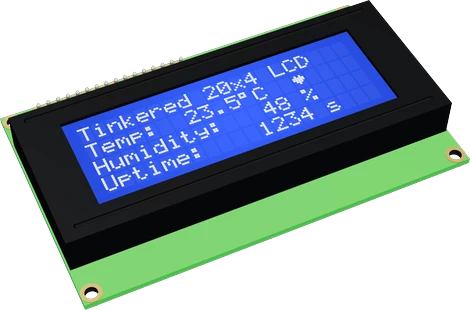
The 2004 LCD is a 5 V module, so on the ESP32 DevKit V1 its VCC goes to VIN while SDA and SCL reach GPIO21 and GPIO22 through a bidirectional level shifter. The shifter is there because the backpack pulls SDA and SCL up to its own 5 V supply, above what the ESP32's pins are rated for.
Wiring the LCD 20x4 (I2C) to the ESP32 DevKit V1
Pin by pin.
| LCD 20x4 (I2C) | ESP32 DevKit V1 | Note |
|---|---|---|
| GND | GND | |
| VCC | VIN | |
| SDA | GPIO21 (D21) | through a level shifter (a BSS138 board): the backpack pulls SDA up to its 5 V |
| SCL | GPIO22 (D22) | through a level shifter (a BSS138 board): the backpack pulls SCL up to its 5 V |
- VCC is on VIN, which gives about 5 V only while the board is powered from USB.
- The backpack runs on 5 V: its PCF8574 reads a high from 0.7 × VCC (3.5 V), above a 3.3 V pin, and its pull-ups would put 5 V on the board's SDA and SCL. Put a bidirectional level shifter on both lines, as the rows say.
What to know on the ESP32 DevKit V1
- The glass needs 4.4 V to 5.0 V of drive and the logic 4.5 V to 5.5 V, so 3V3 is not an option: the characters would be faint or invisible.C2004A datasheet, p. 1
- With VCC at 5 V the backpack's pull-ups hold SDA and SCL near 5 V, and an ESP32 input is rated to VDD + 0.3 V. The PCF8574 also wants 0.7 x VCC, 3.5 V, for a high, more than a 3.3 V pin gives, so pull-ups moved to 3.3 V would not do: both lines pass through a BSS138 bidirectional shifter instead.Espressif ESP32 Series Datasheet v5.3, p. 52; TI PCF8574 datasheet SCPS068K, Recommended Operating Conditions
- The backpack's default 0x27 is also a common MCP23017 address. In an ESP32 project with both, move one of them, or put the display on the ESP32's second I2C controller.TI PCF8574 SCPS068K datasheet, p. 14; Espressif ESP32 Series Datasheet v5.3, p. 4
LCD 20x4 (I2C) code for the ESP32 DevKit V1
Compiled for esp32:esp32:esp32 on 2026-10-30.
// LCD 20x4 (I2C) on ESP32 DevKit V1: wiring and a free simulation at https://www.tinkered.ai/components/lcd-2004-i2c/esp32
#include <Wire.h>
#include <LiquidCrystal_I2C.h>

LiquidCrystal_I2C lcd(0x27, 20, 4);   // address, columns, rows

byte degree[8] = { 0b01100, 0b10010, 0b10010, 0b01100, 0, 0, 0, 0 };

void setup() {
  Wire.begin();
  lcd.init();             // the library's entry point: starts Wire and the 20x4 display
  lcd.backlight();               // the backlight stays off until this
  lcd.createChar(0, degree);
  lcd.setCursor(0, 0); lcd.print("Weather station");
  lcd.setCursor(0, 1); lcd.print("Temp:");
  lcd.setCursor(0, 2); lcd.print("Humidity:");
  lcd.setCursor(0, 3); lcd.print("Uptime:");
}

void loop() {
  lcd.setCursor(10, 1); lcd.print("23.5"); lcd.write(0); lcd.print("C ");
  lcd.setCursor(10, 2); lcd.print("48 %  ");
  lcd.setCursor(10, 3); lcd.print(millis() / 1000); lcd.print(" s   ");
  delay(1000);
}
LCD 20x4 (I2C) on the ESP32 DevKit V1: questions
Can I power the 20x4 LCD from the ESP32's 3V3 pin?
No. The module is rated 4.5 V to 5.5 V and its LCD drive needs 4.4 V minimum (C2004A datasheet, p. 1). Use VIN on USB, or a 5 V supply.
Is the 5 V I2C LCD safe on the ESP32's GPIO21 and GPIO22?
Not wired directly: its pull-ups lift the bus to 5 V, above the ESP32's VDD + 0.3 V limit (ESP32 datasheet, p. 52). That is why the page's wiring puts a bidirectional level shifter on SDA and SCL, keeping the display at 5 V and the ESP32 at 3.3 V.
Why does my LCD show nothing on the ESP32?
Check the address (0x27 or the 0x3F of a PCF8574A backpack), call lcd.backlight(), and turn the contrast trimmer: at 5 V it needs adjusting once.
Keep going
This guide as plain Markdown. /components/lcd-2004-i2c/esp32.md