L9110H
An 8-pin H-bridge chip that runs one small DC motor both ways (or two solenoids) from 2.5 V to 12 V at up to 800 mA, with built-in clamp diodes.
- Supply voltage2.5 V to 12 V (6 V typical)
- Continuous current750 mA to 850 mA, 800 mA typical, per output
- Peak current1.5 A typical, 2 A maximum
- Input thresholdsHigh 2.5 V minimum; low 0.7 V maximum (VCC = 9 V)
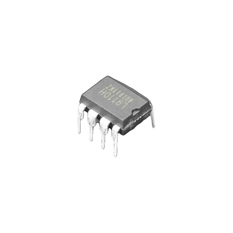
The L9110H is a tiny H-bridge for one DC motor: it runs from 2.5 V to 12 V, gives 800 mA continuous and 1.5 A to 2 A peak per output, and has clamp diodes built in (L9110 datasheet, p. 1). Two inputs, IA and IB, drive outputs OA and OB: one high and one low turns the motor, both low or both high stop it (p. 2). Its inputs read high from 2.5 V (p. 1), so 3.3 V boards drive it even with a 9 V motor supply.
The L9110 holds two push-pull power stages in one DIP-8 (the H suffix) or SOP-8 (the S suffix) package. Wired to the two ends of a motor they form a full H-bridge; used separately they switch two solenoids or relays, and the internal clamp diodes catch the coil's kick (L9110 datasheet, p. 1).
There is no separate logic supply: VCC (pins 2 and 3) powers both the outputs and the input stage, from 2.5 V to 12 V (datasheet, p. 2). The inputs read high from 2.5 V and low below 0.7 V (p. 1), which is why Adafruit could run a 9 V motor from a 3.3 V Feather (Adafruit #4489).
At 800 mA continuous per output (datasheet, p. 2) it suits N20, TT and other small gear motors, toy cars and small pumps. The common HG7881 motor module carries two L9110S chips for two motors, with the same per-channel rules.
L9110H pinout
| Pin | Function | Type |
|---|---|---|
| OA | Motor A side | output |
| VCC1 | 2 (VCC)2.5 V to 12 V | power in |
| VCC2 | 3 (VCC) | power in |
| OB | Motor B side | output |
| GND1 | 5 (GND) | power in |
| IA | PWMHigh from 2.5 V | input |
| IB | PWMHigh from 2.5 V | input |
| GND2 | 8 (GND) | power in |
How to wire the L9110H
Pin by pin, for the board you have.
| L9110H | Arduino Uno | Note |
|---|---|---|
| IA | D5 | |
| IB | D6 | |
| VCC1 | Motor battery + (4 x AA, about 6 V) | Join pins 2 and 3. 100 nF ceramic plus 47 µF electrolytic from VCC to GND at the chip. |
| VCC2 | Motor battery + | |
| GND1 | Battery - and Uno GND | Join pins 5 and 8. |
| GND2 | Battery - and Uno GND | |
| OA | Motor | |
| OB | Motor |
- Run the motor from its own battery, not the Uno's 5V, and share ground.
- Keep each motor's current under 800 mA continuous; a stalled motor exceeds it quickly.
| L9110H | ESP32 DevKit V1 | Note |
|---|---|---|
| IA | GPIO25 (D25) | |
| IB | GPIO26 (D26) | |
| VCC1 | Motor battery + (4 x AA, about 6 V) | Join pins 2 and 3; 100 nF plus 47 µF to GND at the chip. |
| VCC2 | Motor battery + | |
| GND1 | Battery - and ESP32 GND | |
| GND2 | Battery - and ESP32 GND | |
| OA | Motor | |
| OB | Motor |
- IA and IB are inputs only: a 3.3 V high (above the 2.5 V threshold) drives them, and no motor voltage comes back to the ESP32.
| L9110H | Raspberry Pi Pico | Note |
|---|---|---|
| IA | GP6 | |
| IB | GP7 | |
| VCC1 | Motor battery + (4 x AA, about 6 V) | Join pins 2 and 3; 100 nF plus 47 µF to GND at the chip. |
| VCC2 | Motor battery + | |
| GND1 | Battery - and Pico GND | |
| GND2 | Battery - and Pico GND | |
| OA | Motor | |
| OB | Motor |
- Keep the motor battery off VSYS and VBUS; share only ground.
L9110H code
Every example here compiles for its board.
// L9110H on Arduino Uno: wiring and a free simulation at https://www.tinkered.ai/components/l9110h
// L9110H on an Arduino Uno: IA D5, IB D6. speed -255..255; 0 = both inputs low (stop).
const int IA = 5, IB = 6;

void setMotor(int speed) {
  speed = constrain(speed, -255, 255);
  if (speed > 0) {        // IA high, IB low: OA high, OB low
    analogWrite(IA, speed);
    digitalWrite(IB, LOW);
  } else if (speed < 0) { // IA low, IB high: reverse
    digitalWrite(IA, LOW);
    analogWrite(IB, -speed);
  } else {
    digitalWrite(IA, LOW);
    digitalWrite(IB, LOW);
  }
}

void setup() {
  Serial.begin(115200);
  pinMode(IA, OUTPUT);
  pinMode(IB, OUTPUT);
  setMotor(0);
  Serial.println("L9110H ready");
}

void loop() {
  setMotor(200);  Serial.println("Forward"); delay(2000);
  setMotor(0);    Serial.println("Stop");    delay(1000);
  setMotor(-200); Serial.println("Reverse"); delay(2000);
  setMotor(0);    Serial.println("Stop");    delay(1000);
}
// L9110H on ESP32 DevKit V1: wiring and a free simulation at https://www.tinkered.ai/components/l9110h
// L9110H on an ESP32 DevKit V1: IA GPIO25, IB GPIO26. speed -255..255; 0 = stop.
const int IA = 25, IB = 26;

void setMotor(int speed) {
  speed = constrain(speed, -255, 255);
  if (speed > 0) {
    analogWrite(IA, speed);
    analogWrite(IB, 0);
  } else if (speed < 0) {
    analogWrite(IA, 0);
    analogWrite(IB, -speed);
  } else {
    analogWrite(IA, 0);
    analogWrite(IB, 0);
  }
}

void setup() {
  Serial.begin(115200);
  pinMode(IA, OUTPUT);
  pinMode(IB, OUTPUT);
  setMotor(0);
  Serial.println("L9110H ready");
}

void loop() {
  setMotor(200);  Serial.println("Forward"); delay(2000);
  setMotor(0);    Serial.println("Stop");    delay(1000);
  setMotor(-200); Serial.println("Reverse"); delay(2000);
  setMotor(0);    Serial.println("Stop");    delay(1000);
}
// L9110H on Raspberry Pi Pico: wiring and a free simulation at https://www.tinkered.ai/components/l9110h
// L9110H on a Raspberry Pi Pico (arduino-pico): IA GP6, IB GP7. speed -255..255; 0 = stop.
const int IA = 6, IB = 7;

void setMotor(int speed) {
  speed = constrain(speed, -255, 255);
  if (speed > 0) {
    analogWrite(IA, speed);
    analogWrite(IB, 0);
  } else if (speed < 0) {
    analogWrite(IA, 0);
    analogWrite(IB, -speed);
  } else {
    analogWrite(IA, 0);
    analogWrite(IB, 0);
  }
}

void setup() {
  Serial.begin(115200);
  analogWriteRange(255);
  pinMode(IA, OUTPUT);
  pinMode(IB, OUTPUT);
  setMotor(0);
  Serial.println("L9110H ready");
}

void loop() {
  setMotor(200);  Serial.println("Forward"); delay(2000);
  setMotor(0);    Serial.println("Stop");    delay(1000);
  setMotor(-200); Serial.println("Reverse"); delay(2000);
  setMotor(0);    Serial.println("Stop");    delay(1000);
}
Before you wire it
- Connect both VCC pins (2 and 3) and both GND pins (5 and 8).
- Keep VCC between 2.5 V and 12 V (L9110 datasheet, p. 2), and decouple it with 100 nF plus an electrolytic close to the chip.
- Keep each output under 800 mA continuous; peaks of 1.5 A to 2 A are for start-up only (datasheet, p. 2).
- Share ground between the motor battery and your board.
- Never exceed 12 V on VCC (datasheet, p. 2).
- Never power the motor from a board's 3.3 V pin.
- Never parallel two outputs of different chips without care; use a bigger driver for motors above 800 mA.
- Truth table: IA high, IB low drives OA high; IA low, IB high drives OB high; both low or both high pull both outputs low, which brakes the motor (datasheet, p. 2).
- Each output loses about 0.45 V low and 1.4 V high at 750 mA on 9 V (datasheet, p. 1), so a 9 V supply delivers about 7 V to the motor.
- Built-in clamp diodes on the outputs handle the motor's inductive kick (datasheet, p. 1), so no external flyback diodes are needed.
- A 3.3 V GPIO is above the 2.5 V input-high threshold measured at 9 V (datasheet, p. 1); Adafruit drove a 9 V motor from 3.3 V logic (#4489).
- The PWM input on the active side sets speed; the other input stays low.
Specifications
- Supply voltage
- 2.5 V to 12 V (6 V typical)L9110 datasheet (ASIC Advance), p. 2
- Continuous current
- 750 mA to 850 mA, 800 mA typical, per outputL9110 datasheet (ASIC Advance), p. 2
- Peak current
- 1.5 A typical, 2 A maximumL9110 datasheet (ASIC Advance), p. 2
- Input thresholds
- High 2.5 V minimum; low 0.7 V maximum (VCC = 9 V)L9110 datasheet (ASIC Advance), p. 1
- Output levels at 750 mA, VCC 9 V
- High 7.5 V to 7.7 V; low 0.35 V to 0.55 VL9110 datasheet (ASIC Advance), p. 1
- Truth table
- IA/IB: H/L OA high; L/H OB high; L/L and H/H both outputs lowL9110 datasheet (ASIC Advance), p. 2
- Quiescent current
- 2 µA maximumL9110 datasheet (ASIC Advance), p. 2
- Pinout (DIP-8)
- 1 OA, 2 VCC, 3 VCC, 4 OB, 5 GND, 6 IA, 7 IB, 8 GNDL9110 datasheet (ASIC Advance), p. 1
- Operating temperature
- 0 °C to 80 °CL9110 datasheet (ASIC Advance), p. 1
From the L9110 Motor control driver chip datasheet (ASIC Advance), published by ASIC Advance (Shenzhen).
Common mistakes
Only one VCC or GND pin wired
The DIP-8 has two VCC pins (2, 3) and two GND pins (5, 8) (datasheet, p. 1). Leaving one open halves the current path and makes the chip run hot.
Motor too large
At 800 mA continuous (datasheet, p. 2), the L9110 suits small gear motors. A 12 V motor that stalls at 2 A or more burns it out; use a DRV8871 or TB6612FNG.
Expecting coast with both inputs low
Both low pulls both outputs low (datasheet, p. 2), shorting the motor terminals, which brakes it. There is no high-impedance coast state.
Motor noise resetting the board
Brushed motors throw noise onto the supply. Add a 100 nF capacitor across the motor and the supply, and keep the motor battery separate from the board's.
L9110H questions
L9110 vs L298N: which is better for small motors?
For small motors under 800 mA, the L9110 is smaller, cheaper and loses less voltage. The L298N handles two motors at higher voltage and current but is large and inefficient.
Does the L9110H work with 3.3 V logic?
Yes. Its inputs read high from 2.5 V (L9110 datasheet, p. 1), and Adafruit controlled a 9 V motor from a 3.3 V board (#4489).
What is the difference between L9110H and L9110S?
The H is the through-hole DIP-8 chip for breadboards; the S is the SOP-8 surface-mount version found on HG7881 motor modules. Electrically they are the same L9110.
Can I drive a stepper motor with L9110 chips?
A small bipolar stepper, yes: one L9110 per coil, four inputs stepped in sequence. Keep coil current under 800 mA.
Build something with the L9110H
- Build this
Mini fan with speed control
Run a small DC fan at variable speed and direction.
- Build this
Toy car
Two L9110H chips drive a two-wheel toy car.
- Build this
Automatic door latch
Drive a small geared motor to lock and unlock.
This page as plain Markdown, for ChatGPT, Claude or your own agent. /components/l9110h.md