KY-005 IR Transmitter
The KY-005 is a 940 nm infrared LED on a 3-pin board for sending TV and air-conditioner remote codes from an Arduino.
- EmitterInfrared LED, 940 nm
- Forward voltage1.1 V
- Forward current20 mA
- Series resistor220 Ω at 5 V, 120 Ω at 3.3 V
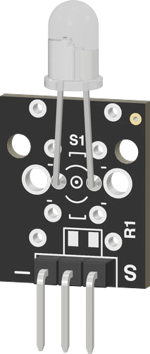
The KY-005 is a 940 nm infrared LED on a small board, rated 1.1 V forward voltage and 20 mA, used to send remote-control codes (Joy-IT KY-005 sensor kit page). Wire S to a digital pin (D3 on an Uno in the IRremote examples) and the "-" pin to GND through a series resistor, 220 Ω on 5 V or 120 Ω on 3.3 V (Joy-IT), then send frames with the IRremote library's IrSender.sendNEC() on a 38 kHz carrier (IRremote README).
The KY-005 is the transmit half of the classic Arduino infrared pair: a 5 mm infrared LED emitting at 940 nm, invisible to the eye, mounted on a small board with a 3-pin header (Joy-IT KY-005 sensor kit page). Pointed at a TV, a set-top box, an air conditioner or another board's IR receiver such as a VS1838B, it replays remote-control codes so a microcontroller can act as a universal remote.
Electrically the module is just the LED. Joy-IT rates it at 1.1 V forward voltage and 20 mA, and asks for a series resistor sized to the supply: 220 Ω at 5 V, 120 Ω at 3.3 V. The board has a pad above the header where that resistor can be soldered; on most boards sold it ships empty, so the resistor goes in the wiring between the "-" pin and ground (Joy-IT). S is the LED's anode, driven by the microcontroller pin.
A remote-control frame is a 38 kHz carrier switched on and off in marks and spaces; an IR receiver module only responds to light flashing near its carrier frequency. The IRremote library generates that carrier and encodes NEC, Sony, RC5, Samsung and other protocols. In IRremote 4.x the carrier is made in software, so any output pin can send; with SEND_PWM_BY_TIMER it uses a hardware timer pin instead, pin 3 on an ATmega328 Uno or Nano and pin 9 on a Mega (IRremote README).
KY-005 IR Transmitter pinout
| Pin | Function | Type |
|---|---|---|
| GND | GND ("−": the LED's cathode, ground it through a series resistor) | power in |
| MID | GND via R1 (middle: the LED's cathode through the R1 pad, empty as sold) | passive |
| S | Digital, PWM | input |
How to wire the KY-005 IR Transmitter
Pin by pin, for the board you have.
| KY-005 IR Transmitter | Arduino Uno | Note |
|---|---|---|
| S | D3 | |
| GND | GND | through a 220 Ω resistor |
| KY-005 IR Transmitter | ESP32 DevKit V1 | Note |
|---|---|---|
| S | GPIO13 (D13) | |
| GND | GND | through a 120 Ω resistor |
| KY-005 IR Transmitter | Raspberry Pi Pico | Note |
|---|---|---|
| S | GP0 | |
| GND | GND | through a 220 Ω resistor |
- An RP2040 pin drives 4 mA by default and 12 mA at most. Keep the 220 Ω resistor here, which lets the LED take about 10 mA, and set the pin to 12 mA drive as the sketch does; 120 Ω would ask about 18 mA.
KY-005 IR Transmitter code
Every example here compiles for its board.
// KY-005 IR Transmitter on Arduino Uno: wiring and a free simulation at https://www.tinkered.ai/components/ky-005-ir-transmitter
#include <Arduino.h>
#include <IRremote.hpp>

const uint8_t SEND_PIN = 3;     // D3 on an Uno or Nano (timer 2), D9 on a Mega

void setup() {
  Serial.begin(115200);
  IrSender.begin(SEND_PIN);
  Serial.println("IR sender ready");
}

uint8_t command = 0x02;

void loop() {
  IrSender.sendNEC(0x00, command, 0);   // address 0x00, the command, no repeats
  Serial.print("sent NEC 0x00 0x");
  Serial.println(command, HEX);
  command++;
  delay(1000);
}
// KY-005 IR Transmitter on ESP32 DevKit V1: wiring and a free simulation at https://www.tinkered.ai/components/ky-005-ir-transmitter
#include <Arduino.h>
#include <IRremote.hpp>

const uint8_t SEND_PIN = 13;    // GPIO13 to S; "-" to GND through 120 Ω (about 18 mA)

void setup() {
  Serial.begin(115200);
  IrSender.begin(SEND_PIN);
  Serial.println("IR sender ready");
}

uint8_t command = 0x02;

void loop() {
  IrSender.sendNEC(0x00, command, 0);   // address 0x00, the command, no repeats
  Serial.print("sent NEC 0x00 0x");
  Serial.println(command, HEX);
  command++;
  delay(1000);
}
// KY-005 IR Transmitter on Raspberry Pi Pico: wiring and a free simulation at https://www.tinkered.ai/components/ky-005-ir-transmitter
#include <Arduino.h>
#include <IRremote.hpp>
#include <hardware/gpio.h>

const uint8_t SEND_PIN = 0;     // GP0 to S; "-" to GND through 220 Ω (about 10 mA)

void setup() {
  Serial.begin(115200);
  IrSender.begin(SEND_PIN);
  // an RP2040 pin drives 4 mA by default and 12 mA at most: set 12 mA for the LED's 10 mA
  gpio_set_drive_strength(SEND_PIN, GPIO_DRIVE_STRENGTH_12MA);
  Serial.println("IR sender ready");
}

uint8_t command = 0x02;

void loop() {
  IrSender.sendNEC(0x00, command, 0);   // address 0x00, the command, no repeats
  Serial.print("sent NEC 0x00 0x");
  Serial.println(command, HEX);
  command++;
  delay(1000);
}
Before you wire it
- S → the send pin, "−" → a resistor → GND (220 Ω on a 5 V board or a Pico, 120 Ω on an ESP32).
- #include <IRremote.hpp>, IrSender.begin(SEND_PIN);, then IrSender.sendNEC(address, command, repeats); (or sendSony, sendRC5, sendSamsung, sendRaw). Leave about 40 ms between frames.
- IRremote cannot receive while it sends on the same board: to check a frame, receive it on another board, or time a receiver's OUT yourself.
- No middle pin as a supply or as ground with R1 empty: it reaches nothing.
- No "−" or the middle pin on 5V/3V3: they are the cathode (the LED reversed).
- No breadboard holes: list it by type, placement is automatic.
- Connect S to the send pin and the "-" pin to GND through a series resistor: 220 Ω on a 5 V board, 120 Ω on a 3.3 V board (Joy-IT KY-005 page). That keeps the LED near its 20 mA rating.
- The middle pin reaches the LED's cathode only through the board's resistor pad. If you solder a resistor there, wire the middle pin to GND instead; with the pad empty the middle pin connects to nothing.
- IRremote's default polarity is pin, resistor, LED, ground: the pin goes HIGH for an active mark (IRremote README). Do not wire the LED from VCC to the pin unless you enable USE_ACTIVE_LOW_OUTPUT_FOR_SEND_PIN.
- For more range, IRremote's author suggests two or three IR LEDs in series from 5 V (130 Ω for two at 20 mA) or a transistor driver for currents above 20 mA (IRremote README).
- Aim the LED at the receiver: its light is directional and invisible, so check that it fires by viewing it through a phone camera, which shows the IR flashes as purple light.
- IRremote can send from any output pin by default.
- On a Raspberry Pi Pico keep 220 Ω: an RP2040 pin is rated for 12 mA at its strongest drive setting (4 mA by default), and 220 Ω holds the LED to about 10 mA. On an ESP32, 120 Ω gives about 18 mA.
Specifications
- Emitter
- Infrared LED, 940 nmJoy-IT KY-005 sensor kit page
- Forward voltage
- 1.1 VJoy-IT KY-005 sensor kit page
- Forward current
- 20 mAJoy-IT KY-005 sensor kit page
- Series resistor
- 220 Ω at 5 V, 120 Ω at 3.3 VJoy-IT KY-005 sensor kit page
- Pins
- S (LED anode), middle (via resistor pad), "-" (LED cathode)Joy-IT KY-005 sensor kit page; board layout
- Typical carrier
- 38 kHz (generated by IRremote)IRremote library README
- Send pin (IRremote 4.x)
- Any pin by default; pin 3 on Uno/Nano, 9 on Mega with SEND_PWM_BY_TIMERIRremote library README, Send pin and timer tables
- Supply voltage
- 3.3–5 V
- Maximum supply voltage
- 5.5 V
- Interface
- Digital
- Dimensions
- 15 × 6.82 × 34.6 mm
- Weight
- 1.5 g
From the Generic (KY-005 / Joy-IT)'s datasheet, published by Generic (KY-005 / Joy-IT).
Common mistakes
No series resistor
The LED drops only 1.1 V at 20 mA (Joy-IT). Wired straight from a 5 V pin to GND it draws far more than its rating and more than an AVR pin should source. Use 220 Ω at 5 V or 120 Ω at 3.3 V.
Wiring the cathode to the supply
S is the anode and "-" the cathode. Reversed, the LED never lights and the sketch seems to send nothing. S goes to the signal pin, "-" through the resistor to ground.
Using the middle pin with no resistor fitted
The middle pin connects to the cathode only through the resistor pad, which is usually empty. Grounding it alone leaves the LED unconnected.
Expecting to see it light up
940 nm is outside human vision (Joy-IT). A working transmitter looks dark. Check it through a phone camera or with an IR receiver on a second board.
Old IRremote examples
Tutorials written for IRremote 2.x pass a raw 32-bit NEC value (irsend.sendNEC(0x20DF10EF, 32)), an API the 4.x library has replaced. Use #include <IRremote.hpp>, IrSender.begin(pin) and IrSender.sendNEC(address, command, repeats) as the current README shows.
KY-005 IR Transmitter questions
How do I connect a KY-005 to an Arduino Uno?
S to D3 and "-" to GND through a 220 Ω resistor (Joy-IT KY-005 page). Then #include <IRremote.hpp>, call IrSender.begin(3) in setup() and IrSender.sendNEC(address, command, repeats) to send a frame. D3 is the pin IRremote's Uno examples use and its timer 2 output (IRremote README).
Can I use the KY-005 with an ESP32 or Raspberry Pi Pico at 3.3 V?
Yes. Use a 120 Ω series resistor at 3.3 V, as Joy-IT specifies for this LED, to keep it near 20 mA. IRremote generates the carrier on any pin of an ESP32 or RP2040 (IRremote README), and Joy-IT documents GPIO17 on the Pico with the micropython-ir library.
What resistor does the KY-005 need?
220 Ω on 5 V and 120 Ω on 3.3 V (Joy-IT KY-005 page). With the LED's 1.1 V forward voltage that gives about 18 mA, just under its 20 mA rating.
Why does my TV not respond to the KY-005?
Check that the sketch sends the TV's own protocol, address and command (decode its remote first with an IR receiver), that S is on the send pin with the right polarity, that the series resistor is in place, and that the LED points at the TV within a few metres. A phone camera shows whether the LED is flashing at all.
What carrier frequency does the KY-005 use?
The board has no oscillator: the sketch makes the carrier. IRremote produces 38 kHz for most protocols (IRremote README), the frequency common receiver modules are tuned to.
How do I get more range from a KY-005?
Drive more LED current through a transistor rather than the GPIO, or put two or three IR LEDs in series from 5 V; IRremote's README gives 130 Ω for two LEDs at 20 mA. Pointing the LED straight at the receiver matters as much as current.
Build something with the KY-005 IR Transmitter
- Build this
Universal TV remote
Learn codes with an IR receiver, then replay them from buttons or a schedule with the KY-005.
- Build this
Smart air-conditioner controller
Send the AC's on, off and temperature frames from an ESP32 driven by a phone app or a room sensor.
- Build this
IR link between two boards
Send short commands from one Arduino to another across a room with a KY-005 and a receiver module.
- Build this
Camera shutter trigger
Fire a camera that accepts an IR remote for time-lapse or motion-triggered photos.
This page as plain Markdown, for ChatGPT, Claude or your own agent. /components/ky-005-ir-transmitter.md