KY-005 IR Transmitter with an ESP32 DevKit V1
The KY-005 is a 940 nm infrared LED on a 3-pin board for sending TV and air-conditioner remote codes from an Arduino.
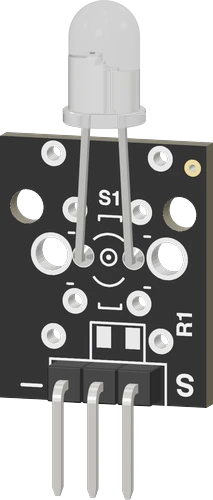
On the ESP32 DevKit V1 the KY-005's S pin goes to GPIO13 and its GND pin to ground through 120 Ω, the value Joy-IT gives for a 3.3 V board, which lets about 18 mA through the 1.1 V infrared LED. The sketch starts IRremote with IrSender.begin(13) and sends one NEC frame a second, raising the command byte each time.
Wiring the KY-005 IR Transmitter to the ESP32 DevKit V1
Pin by pin.
| KY-005 IR Transmitter | ESP32 DevKit V1 | Note |
|---|---|---|
| S | GPIO13 (D13) | |
| GND | GND | through a 120 Ω resistor |
What to know on the ESP32 DevKit V1
- From a 3.3 V pin, (3.3 V minus 1.1 V) / 120 Ω is about 18 mA, just under the LED's 20 mA rating. The 220 Ω used with a 5 V Uno would pass only about 10 mA here and shorten the range.Joy-IT KY-005 sensor kit page
- IRremote drives the send pin HIGH for each mark, which fits this wiring: GPIO13 to S, the LED, then the 120 Ω resistor to GND. An LED wired from 3V3 down to the pin would need USE_ACTIVE_LOW_OUTPUT_FOR_SEND_PIN defined before the include.IRremote library README, Polarity of send pin
- On an ESP32, IRremote turns on SEND_PWM_BY_TIMER by itself and builds the carrier with the LEDC peripheral, which can drive any output pin. With arduino-esp32 2.x it takes LEDC channel 0, so leave that channel to it if the sketch also dims LEDs with ledcSetup().IRremote library README, Send pin; IRremote src/IRremote.hpp and src/private/IRTimer.hpp
- IRremote sends its carrier at a 30 % duty cycle, so the LED sees its 18 mA peak only in short pulses and its average current during a frame is much lower than the resistor calculation suggests.IRremote library README, Why do we use 30% duty cycle for sending
KY-005 IR Transmitter code for the ESP32 DevKit V1
Compiled for esp32:esp32:esp32 on 2026-10-30.
// KY-005 IR Transmitter on ESP32 DevKit V1: wiring and a free simulation at https://www.tinkered.ai/components/ky-005-ir-transmitter/esp32
#include <Arduino.h>
#include <IRremote.hpp>

const uint8_t SEND_PIN = 13;    // GPIO13 to S; "-" to GND through 120 Ω (about 18 mA)

void setup() {
  Serial.begin(115200);
  IrSender.begin(SEND_PIN);
  Serial.println("IR sender ready");
}

uint8_t command = 0x02;

void loop() {
  IrSender.sendNEC(0x00, command, 0);   // address 0x00, the command, no repeats
  Serial.print("sent NEC 0x00 0x");
  Serial.println(command, HEX);
  command++;
  delay(1000);
}
KY-005 IR Transmitter on the ESP32 DevKit V1: questions
Why 120 Ω on the ESP32 when the Uno uses 220 Ω?
The ESP32 drives the LED from 3.3 V instead of 5 V, leaving only 2.2 V across the resistor after the LED's 1.1 V. Joy-IT lists 120 Ω for 3.3 V boards, which brings the current back to about 18 mA.
How can I tell the KY-005 is actually sending?
Its 940 nm light is invisible to the eye (Joy-IT), but most phone cameras show it: watch the LED through the camera and it flashes once a second as the sketch sends each frame. The serial monitor at 115200 baud also prints each command sent.
Can I use another ESP32 pin for the KY-005?
Any pin that can be an output works, since IRremote allows every ESP32 pin for sending (README, timer and pin usage table). GPIO34 to GPIO39 are inputs only on the ESP32 (Espressif datasheet, p. 14), so they cannot send.
Keep going
This guide as plain Markdown. /components/ky-005-ir-transmitter/esp32.md