IR Receiver Module (VS1838B)
A three-pin 38 kHz infrared receiver board that turns TV-remote button presses into clean digital pulses.
- ModuleIDUINO ST1089, 3 pins, 25 × 12 mm, 2 g
- PinoutS signal, + power (middle pin), - ground
- Receiver supply (VS1838B)2.7 V to 5.5 V; absolute maximum 6.0 V
- Carrier frequency38 kHz
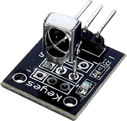
The IDUINO ST1089 is a 25 × 12 mm breakout for the VS1838B, a 38 kHz infrared remote-control receiver rated 2.7 V to 5.5 V with a typical 20 m range and a ±45° reception angle (IDUINO ST1089 sheet, p. 1; VS1838B datasheet, p. 2). Wire S to any digital pin, + (the middle pin) to 5 V on an Arduino or 3.3 V on an ESP32, and - to GND, then decode the pulses with a library such as IRremote (ST1089 sheet, p. 1).
The ST1089 is IDUINO's infrared receiver module, its version of the board sensor kits sell as the KY-022: a VS1838B receiver on a small black breakout with a three-pin header labelled S, + and -, the + in the middle (IDUINO ST1089 sheet, p. 1). It is the part that lets a project react to a TV remote, a cheap kit remote or IDUINO's own ST1087 transmitter module.
The VS1838B pairs its photodiode with an amplifier, a 38 kHz band-pass filter 2 to 5 kHz wide (VS1838B datasheet, p. 2) and a demodulator. Remote controls send their codes as bursts of 38 kHz infrared light; the receiver strips the carrier and hands the microcontroller only the envelope, so the S pin sits high when nothing arrives and pulls low for the length of each burst. A library such as IRremote times those low pulses and turns them into a protocol, an address and a command.
The receiver is rated 2.7 V to 5.5 V, draws 0.4 mA typical, accepts light within ±45° and reaches 18 m minimum, 20 m typical in its maker's test (VS1838B datasheet, p. 2). IDUINO's sheet gives the module's operation voltage as 5 V (p. 1); because the chip works down to 2.7 V, the board also runs from a 3.3 V board's supply, which keeps its output at 3.3 V logic.
IR Receiver Module (VS1838B) pinout
| Pin | Function | Type |
|---|---|---|
| GND | - (GND) | power in |
| VCC | + (5V)2.7–5 V | power in |
| OUT | Digital | open collector |
How to wire the IR Receiver Module (VS1838B)
Pin by pin, for the board you have.
| IR Receiver Module (VS1838B) | Arduino Uno | Note |
|---|---|---|
| OUT | D2 | |
| GND | GND | |
| VCC | 5V |
| IR Receiver Module (VS1838B) | ESP32 DevKit V1 | Note |
|---|---|---|
| OUT | GPIO13 (D13) | |
| GND | GND | |
| VCC | 3V3 |
| IR Receiver Module (VS1838B) | Raspberry Pi Pico | Note |
|---|---|---|
| OUT | GP0 | |
| GND | GND | |
| VCC | 3V3 |
IR Receiver Module (VS1838B) code
Every example here compiles for its board.
// IR Receiver Module (VS1838B) on Arduino Uno: wiring and a free simulation at https://www.tinkered.ai/components/ir-receiver-st1089
#define DECODE_NEC
#define DECODE_RC5
#include <IRremote.hpp>          // .hpp, not .h, in 4.x

const int IR_PIN = 2;

void setup() {
  Serial.begin(9600);
  IrReceiver.begin(IR_PIN, ENABLE_LED_FEEDBACK);
}

void loop() {
  if (IrReceiver.decode()) {
    Serial.println(IrReceiver.decodedIRData.command, HEX);   // e.g. 45
    // also: .address, .protocol, .decodedRawData,
    //       .flags & IRDATA_FLAGS_IS_REPEAT
    IrReceiver.resume();                                     // required
  }
}
// IR Receiver Module (VS1838B) on ESP32 DevKit V1: wiring and a free simulation at https://www.tinkered.ai/components/ir-receiver-st1089
#define DECODE_NEC
#define DECODE_RC5
#include <IRremote.hpp>          // .hpp, not .h, in 4.x

const int IR_PIN = 13;

void setup() {
  Serial.begin(9600);
  IrReceiver.begin(IR_PIN, ENABLE_LED_FEEDBACK);
}

void loop() {
  if (IrReceiver.decode()) {
    Serial.println(IrReceiver.decodedIRData.command, HEX);   // e.g. 45
    // also: .address, .protocol, .decodedRawData,
    //       .flags & IRDATA_FLAGS_IS_REPEAT
    IrReceiver.resume();                                     // required
  }
}
// IR Receiver Module (VS1838B) on Raspberry Pi Pico: wiring and a free simulation at https://www.tinkered.ai/components/ir-receiver-st1089
#define DECODE_NEC
#define DECODE_RC5
#include <IRremote.hpp>          // .hpp, not .h, in 4.x

const int IR_PIN = 0;

void setup() {
  Serial.begin(9600);
  IrReceiver.begin(IR_PIN, ENABLE_LED_FEEDBACK);
}

void loop() {
  if (IrReceiver.decode()) {
    Serial.println(IrReceiver.decodedIRData.command, HEX);   // e.g. 45
    // also: .address, .protocol, .decodedRawData,
    //       .flags & IRDATA_FLAGS_IS_REPEAT
    IrReceiver.resume();                                     // required
  }
}
// IR Receiver Module (VS1838B) on ESP8266 NodeMCU: wiring and a free simulation at https://www.tinkered.ai/components/ir-receiver-st1089
#include <IRremoteESP8266.h>
#include <IRrecv.h>
#include <IRutils.h>

const uint16_t kRecvPin = 15;
IRrecv irrecv(kRecvPin);
decode_results results;

void setup() {
  Serial.begin(115200);
  irrecv.enableIRIn();
}

void loop() {
  if (irrecv.decode(&results)) {
    Serial.println(resultToHumanReadableBasic(&results));
    irrecv.resume();
  }
}
// IR Receiver Module (VS1838B) on STM32 Blue Pill (F103C8): wiring and a free simulation at https://www.tinkered.ai/components/ir-receiver-st1089
#include <Arduino.h>
#include <IRremote.hpp>

void setup() {
  Serial.begin(115200);
  IrReceiver.begin(PB0, DISABLE_LED_FEEDBACK);
}
void loop() {
  if (IrReceiver.decode()) {
    Serial.println(IrReceiver.decodedIRData.command, HEX);
    IrReceiver.resume();
  }
}
Before you wire it
- OUT is active LOW: it idles HIGH and pulses LOW while a modulated burst arrives. The receiver demodulates the 38kHz carrier itself, so the sketch only ever sees the envelope.
- Both expose OUT / VCC / GND.
- Pin order differs between them, so always wire by pin NAME, never by position. The breakout's silkscreen reads S / + / - and those map to OUT / VCC / GND.
- VCC goes to 5V on an AVR board and to 3V3 on an ESP32.
- Call resume() after every successful decode or the receiver stays stopped and no further frames arrive.
- Position the sensor with line of sight to the remote.
- Power it from the board's logic voltage: its output pull-up goes to its supply
- Power it from the board's logic voltage
- Do not expect OUT to go HIGH on reception. It is active LOW.
- Do not use the 2.x IRremote API on AVR: IRrecv irrecv(pin); irrecv.enableIRIn(); irrecv.decode(&results); Most KY-022 datasheets and tutorials still show it, but IRremote 4.x REMOVED it and that code does not compile. (Confusingly, that 2.x-looking API *is* correct for IRremoteESP8266 on ESP32.)
- Do not use tone() on an AVR board in the same sketch: IRremote 4.x drives TIMER2 and so does tone(). Use a different sounder pin strategy or drop one of them.
- Power + from the board's logic voltage: 5 V on an Arduino Uno, Nano or Mega, 3.3 V on an ESP32, ESP8266 or Raspberry Pi Pico. The VS1838B runs from 2.7 V to 5.5 V (VS1838B datasheet, p. 2), and its output high follows its supply, so a 3.3 V supply keeps S safe for 3.3 V GPIOs.
- Wire by the printed labels, not by position: on the ST1089 the + pin is the middle one, S and - sit on either side (IDUINO ST1089 sheet, p. 1). Other receiver boards and bare receivers order their pins differently.
- S is active low: it idles high and pulls low while a 38 kHz burst arrives. Any digital input works; on an Arduino, an interrupt-capable pin such as D2 is a common choice.
- Give it line of sight to the remote within its ±45° reception angle (VS1838B datasheet, p. 2), and keep it away from direct sunlight and strong lamps, which flood its photodiode with infrared.
Specifications
- Module
- IDUINO ST1089, 3 pins, 25 × 12 mm, 2 gIDUINO ST1089 sheet, p. 1
- Pinout
- S signal, + power (middle pin), - groundIDUINO ST1089 sheet, p. 1
- Receiver supply (VS1838B)
- 2.7 V to 5.5 V; absolute maximum 6.0 VVS1838B datasheet, p. 2
- Carrier frequency
- 38 kHzVS1838B datasheet, p. 2
- Reception distance
- 18 m min, 20 m typ (maker's test)VS1838B datasheet, p. 2
- Reception angle
- ±45°VS1838B datasheet, p. 2
- Supply current
- 0.4 mA typ, 1.5 mA maxVS1838B datasheet, p. 2
- Output levels at 5 V
- Low 0.2 V typ (0.4 V max), high 4.5 V minVS1838B datasheet, p. 2
- Operating temperature
- -20 to 85 °CVS1838B datasheet, p. 2
- Supply voltage
- 2.7–5 V
- Maximum supply voltage
- 5.5 V
- Interface
- GPIO pulse timing
- Dimensions
- 15.4 × 15.7 × 24.2 mm
- Weight
- 2 g
From the IDUINO's datasheet, published by IDUINO.
Common mistakes
Using old IRremote example code
Most module sheets, IDUINO's included (ST1089 sheet, p. 2), show the IRremote 2.x API (IRrecv irrecv(pin); irrecv.enableIRIn(); irrecv.decode(&results)). IRremote 4.x removed it, so that code no longer compiles. Use the IrReceiver object: IrReceiver.begin(pin), then IrReceiver.decode() and IrReceiver.decodedIRData.command.
Forgetting resume() after a decode
After each successful decode the library stops listening until you call IrReceiver.resume() (or irrecv.resume() in IRremoteESP8266). Without it the first button works and nothing after it does.
Expecting S to go high on a signal
The output is active low: it rests high and pulses low while infrared bursts arrive. Code that waits for a high pulse never sees one.
Using tone() in the same Arduino sketch
On AVR boards IRremote 4.x uses Timer2 for receiving, and so does tone(). The two fight and decoding fails. Drop one, or drive the buzzer another way.
Using a remote on another carrier
The VS1838B is tuned to 38 kHz with a few kilohertz of bandwidth (VS1838B datasheet, p. 2). Most TV and kit remotes use 38 kHz; a remote on a distant carrier frequency barely registers or not at all.
IR Receiver Module (VS1838B) questions
Can I use the IR receiver module with a 3.3 V board like an ESP32?
Yes. The VS1838B on the module is rated 2.7 V to 5.5 V (VS1838B datasheet, p. 2), so power + from the ESP32's 3V3 pin and the S output swings to 3.3 V. Use the IRremoteESP8266 library on an ESP32 or ESP8266.
Why does my IR receiver decode nothing?
Check that S, + and - follow the printed labels, + being the middle pin (IDUINO ST1089 sheet, p. 1), that the sketch reads the pin S is wired to, that it calls resume() after each decode, and that it uses the IRremote 4.x API. Then point the remote straight at the receiver within ±45° (VS1838B datasheet, p. 2), away from sunlight.
What is the range of the IR receiver module?
The VS1838B datasheet gives 18 m minimum and 20 m typical in its test (p. 2), within a ±45° reception angle. In practice a cheap kit remote with a weak LED reaches less, and the range drops sharply off-axis.
Is the ST1089 the same as the KY-022?
Both are three-pin VS1838B receiver boards labelled S, + and - with the same 38 kHz receiver, and they wire and code the same way. Always check the silkscreen, because pin order varies between makers' boards.
Which remote controls work with it?
Any remote that sends on a 38 kHz carrier, which covers most TV, air conditioner and kit remotes (VS1838B datasheet, p. 2). The IRremote library decodes NEC, Sony, RC5, RC6, Samsung and other common protocols, and prints the raw timing for the rest.
Build something with the IR Receiver Module (VS1838B)
- Build this
Remote-controlled LEDs
Map the buttons of a cheap kit remote to colours or brightness of an LED strip.
- Build this
IR-controlled robot car
Drive a rover forward, back and around with the arrow keys of a TV remote.
- Build this
Remote code reader
Print the protocol, address and command of every button to learn a remote's codes.
- Build this
Universal remote
Record codes with the receiver and replay them through a KY-005 or ST1087 IR transmitter.
This page as plain Markdown, for ChatGPT, Claude or your own agent. /components/ir-receiver-st1089.md