Keypad 4×3
A 12-key phone-style membrane keypad (0 to 9, * and #) wired as a 4-row by 3-column matrix on a 7-pin ribbon.
- Keys12, telephone layout 1 to 9, *, 0, #
- Matrix4 rows × 3 columns, 7 pins to scan
- PinoutPins 1 to 4 = R1 to R4, pins 5 to 7 = C1 to C3
- Size70 × 77 × 1 mm, adhesive backing
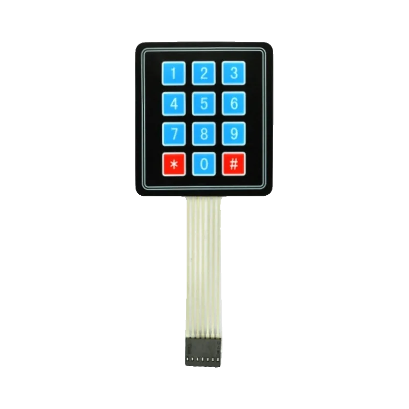
The 4×3 membrane keypad has 12 keys in a phone layout wired as a matrix, so 7 pins read all of them: pins 1 to 4 are rows R1 to R4 and pins 5 to 7 are columns C1 to C3 (Adafruit Matrix Keypad guide, Pinouts; Adafruit product 419). It is purely passive switches with no supply pin, so it works at the logic level of any board, using the microcontroller's internal pull-ups. The Keypad library scans it and returns the key pressed.
Each key sits where a row trace crosses a column trace; pressing it joins the two. Instead of 12 inputs, the microcontroller drives the three columns low one at a time and reads the four rows, finding the pressed key from which row goes low. Adafruit's version is a thin adhesive-backed membrane, 70 × 77 × 1 mm, on an 85 mm ribbon with a 7-pin 0.1-inch connector (Adafruit product 419).
Because there is no power pin and nothing active on the keypad, it is safe on 5 V and 3.3 V boards alike. The Keypad library enables the internal pull-ups on the row pins, scans the matrix, debounces the keys and hands back a character such as '7' or '#'. Holding several keys at once can create ghost presses on a plain matrix, which matters for games but not for PIN entry.
The pinout runs in order along the ribbon: R1, R2, R3, R4, then C1, C2, C3 (Adafruit Matrix Keypad guide, Pinouts). Some generic 3×4 keypads, especially the hard plastic phone-style ones, scramble that order, so check yours before wiring.
Keypad 4×3 pinout
| Pin | Function | Type |
|---|---|---|
| 1 | Row 1: 1 2 3 | passive |
| 2 | Row 2: 4 5 6 | passive |
| 3 | Row 3: 7 8 9 | passive |
| 4 | Row 4: * 0 # | passive |
| 5 | Column 1: 1 4 7 * | passive |
| 6 | Column 2: 2 5 8 0 | passive |
| 7 | Column 3: 3 6 9 # | passive |
How to wire the Keypad 4×3
Pin by pin, for the board you have.
| Keypad 4×3 | Arduino Uno | Note |
|---|---|---|
| 1 (R1) | D9 | |
| 2 (R2) | D8 | |
| 3 (R3) | D7 | |
| 4 (R4) | D6 | |
| 5 (C1) | D5 | |
| 6 (C2) | D4 | |
| 7 (C3) | D3 |
| Keypad 4×3 | ESP32 DevKit V1 | Note |
|---|---|---|
| 1 (R1) | GPIO13 (D13) | |
| 2 (R2) | GPIO14 (D14) | |
| 3 (R3) | GPIO27 (D27) | |
| 4 (R4) | GPIO26 (D26) | |
| 5 (C1) | GPIO25 (D25) | |
| 6 (C2) | GPIO33 (D33) | |
| 7 (C3) | GPIO32 (D32) |
- Do not use GPIO34 to GPIO39 for rows: they have no internal pull-ups, which the Keypad library relies on.
| Keypad 4×3 | Raspberry Pi Pico | Note |
|---|---|---|
| 1 (R1) | GP2 | |
| 2 (R2) | GP3 | |
| 3 (R3) | GP4 | |
| 4 (R4) | GP5 | |
| 5 (C1) | GP6 | |
| 6 (C2) | GP7 | |
| 7 (C3) | GP8 |
Keypad 4×3 code
Every example here compiles for its board.
// Keypad 4×3 on Arduino Uno: wiring and a free simulation at https://www.tinkered.ai/components/keypad-4x3
// 4x3 membrane keypad on an Arduino Uno: rows D9 D8 D7 D6, columns D5 D4 D3
// Type a 4-digit code and press # to check it; * clears.
#include <Keypad.h>

const byte ROWS = 4;
const byte COLS = 3;
char keys[ROWS][COLS] = {
  {'1', '2', '3'},
  {'4', '5', '6'},
  {'7', '8', '9'},
  {'*', '0', '#'}
};
byte rowPins[ROWS] = {9, 8, 7, 6}; // R1 to R4 (keypad pins 1 to 4)
byte colPins[COLS] = {5, 4, 3};    // C1 to C3 (keypad pins 5 to 7)
Keypad keypad = Keypad(makeKeymap(keys), rowPins, colPins, ROWS, COLS);

const char SECRET[] = "1234";
char entry[5];
byte length = 0;

void setup() {
  Serial.begin(115200);
  Serial.println(F("Enter code, then #"));
}

void loop() {
  char key = keypad.getKey();
  if (!key) return;
  Serial.print(F("Key: "));
  Serial.println(key);
  if (key == '*') {
    length = 0;
    Serial.println(F("Cleared"));
  } else if (key == '#') {
    entry[length] = '\0';
    Serial.println(strcmp(entry, SECRET) == 0 ? F("Access granted") : F("Wrong code"));
    length = 0;
  } else if (length < 4) {
    entry[length++] = key;
  }
}
// Keypad 4×3 on ESP32 DevKit V1: wiring and a free simulation at https://www.tinkered.ai/components/keypad-4x3
// 4x3 membrane keypad on an ESP32 DevKit V1: rows GPIO13 14 27 26, columns GPIO25 33 32
// Type a 4-digit code and press # to check it; * clears.
#include <Keypad.h>

const byte ROWS = 4;
const byte COLS = 3;
char keys[ROWS][COLS] = {
  {'1', '2', '3'},
  {'4', '5', '6'},
  {'7', '8', '9'},
  {'*', '0', '#'}
};
byte rowPins[ROWS] = {13, 14, 27, 26};
byte colPins[COLS] = {25, 33, 32};
Keypad keypad = Keypad(makeKeymap(keys), rowPins, colPins, ROWS, COLS);

const char SECRET[] = "1234";
char entry[5];
byte length = 0;

void setup() {
  Serial.begin(115200);
  Serial.println("Enter code, then #");
}

void loop() {
  char key = keypad.getKey();
  if (!key) return;
  Serial.printf("Key: %c\n", key);
  if (key == '*') {
    length = 0;
    Serial.println("Cleared");
  } else if (key == '#') {
    entry[length] = '\0';
    Serial.println(strcmp(entry, SECRET) == 0 ? "Access granted" : "Wrong code");
    length = 0;
  } else if (length < 4) {
    entry[length++] = key;
  }
}
// Keypad 4×3 on Raspberry Pi Pico: wiring and a free simulation at https://www.tinkered.ai/components/keypad-4x3
// 4x3 membrane keypad on a Raspberry Pi Pico (arduino-pico): rows GP2 to GP5, columns GP6 to GP8
// Type a 4-digit code and press # to check it; * clears.
#include <Keypad.h>

const byte ROWS = 4;
const byte COLS = 3;
char keys[ROWS][COLS] = {
  {'1', '2', '3'},
  {'4', '5', '6'},
  {'7', '8', '9'},
  {'*', '0', '#'}
};
byte rowPins[ROWS] = {2, 3, 4, 5};
byte colPins[COLS] = {6, 7, 8};
Keypad keypad = Keypad(makeKeymap(keys), rowPins, colPins, ROWS, COLS);

const char SECRET[] = "1234";
char entry[5];
byte length = 0;

void setup() {
  Serial.begin(115200);
  Serial.println("Enter code, then #");
}

void loop() {
  char key = keypad.getKey();
  if (!key) return;
  Serial.print("Key: ");
  Serial.println(key);
  if (key == '*') {
    length = 0;
    Serial.println("Cleared");
  } else if (key == '#') {
    entry[length] = '\0';
    Serial.println(strcmp(entry, SECRET) == 0 ? "Access granted" : "Wrong code");
    length = 0;
  } else if (length < 4) {
    entry[length++] = key;
  }
}
Before you wire it
- Wire pins 1 to 4 as rows and 5 to 7 as columns, as Adafruit's pinout shows, and list them in that order in rowPins and colPins.
- Use pins with internal pull-ups for the rows; the Keypad library enables them.
- Keep the keymap array in the same row and column order as the wiring.
- Check a generic keypad's pin order with a multimeter in continuity mode before wiring; not every 3×4 keypad follows the same order.
- Never use ESP32 input-only pins (GPIO34 to GPIO39) as rows: they have no pull-ups.
- Never put the keypad on Uno D0 and D1: they are the USB serial lines.
- Never crease the ribbon tail sharply; the printed traces crack.
- No power or ground pin: the keypad is seven traces and twelve switches, so it adapts to any logic level.
- The library scans columns one at a time; a full scan is fast enough that getKey() can sit in a busy loop.
- Pressing three keys that form a rectangle on the matrix can make a fourth key appear pressed (ghosting); diodes per key would prevent it, but membranes have none.
- For fewer GPIOs, a PCF8574 or MCP23017 I2C expander can scan the 7 lines with the Keypad_I2C variant of the library.
- The adhesive backing sticks to an enclosure face; cut a slot for the ribbon and keep the connector strain-free.
Specifications
- Keys
- 12, telephone layout 1 to 9, *, 0, #Adafruit product 419 page
- Matrix
- 4 rows × 3 columns, 7 pins to scanAdafruit product 419 page
- Pinout
- Pins 1 to 4 = R1 to R4, pins 5 to 7 = C1 to C3Adafruit Matrix Keypad guide, Pinouts (PID 419)
- Size
- 70 × 77 × 1 mm, adhesive backingAdafruit product 419 page
- Cable
- 85 mm including connector, 7-pin 0.1-inch pitchAdafruit product 419 page
- Weight
- 7.5 gAdafruit product 419 page
From the Adafruit Membrane 3x4 Matrix Keypad, product 419, published by Adafruit (product 419).
Common mistakes
Rows and columns swapped
With rows and columns swapped in the code, keys come back wrong or not at all. Adafruit's keypad has R1 to R4 on pins 1 to 4 and C1 to C3 on pins 5 to 7 (Adafruit Matrix Keypad guide, Pinouts).
Assuming every 3×4 keypad has the same pinout
Hard plastic phone-style keypads use a different, mixed pin order. Probe with a continuity tester: pressing '1' should connect the R1 and C1 pins.
Rows on pins without pull-ups
The Keypad library needs internal pull-ups on the row pins. On an ESP32, GPIO34 to GPIO39 have none, so keys read as random presses.
Using D0 or D1 on an Uno
Pins D0 and D1 carry USB serial. A keypad there garbles Serial Monitor output and can block uploads.
Keypad 4×3 questions
What is the 3×4 membrane keypad pinout?
On Adafruit's keypad, pins 1 to 4 are rows R1 to R4 and pins 5 to 7 are columns C1 to C3, counted left to right with the keys facing you (Adafruit Matrix Keypad guide, Pinouts). Generic keypads usually match, but check with a continuity tester.
Does the keypad need 5 V or 3.3 V?
Neither: it has no power pin. It is a matrix of switches read with the microcontroller's own pull-ups, so it works on 5 V and 3.3 V boards alike.
Which library reads a matrix keypad?
Keypad by Mark Stanley and Alexander Brevig (chris--a/Keypad on PlatformIO). Define the keymap, the row and column pins, and call getKey() in the loop.
How many pins does a 4×3 keypad need?
Seven: four rows and three columns (Adafruit product 419). An I2C expander such as the PCF8574 brings that down to two.
4×3 or 4×4 keypad?
The 4×3 has the phone digits plus * and #; the 4×4 adds A to D in a fourth column and needs an eighth pin. The same library and code work for both with a different keymap.
Build something with the Keypad 4×3
- Build this
Keypad door lock
A 4-digit code moves a servo latch and shows status on an LCD.
- Build this
Pico calculator
Add and subtract with * and # as operators.
This page as plain Markdown, for ChatGPT, Claude or your own agent. /components/keypad-4x3.md