HC-05 Bluetooth Module
The HC-05 is a Classic Bluetooth 2.0 serial port module: pair a phone or PC and it turns the link into a 9600 baud UART.
- BluetoothV2.0 + EDR, SPP, CSR BlueCore4-External
- Module supply (bare HC-05)3.3 V, works at 3.0 V to 4.2 V
- ZS-040 carrier supply3.6 V to 6 V (on-board regulator)
- UART logic level3.3 V
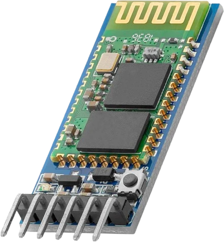
The HC-05 is a Classic Bluetooth 2.0 + EDR module that bridges a phone or PC to a UART, at 9600 baud in data mode and 38400 baud in AT command mode, with pairing PIN 1234 (HC Serial Bluetooth Products user manual, pp. 2, 4, 13). On the common ZS-040 carrier, power VCC from 5 V, wire the module's TXD to the board's RX and the board's TX to RXD through a 1 kΩ / 2 kΩ divider, because the module's logic runs at 3.3 V (manual, p. 11).
The HC-05 is a Bluetooth Serial Port Profile (SPP) module: once a phone, tablet or PC pairs with it, every byte the microcontroller writes to the module's UART reaches the other device, and every byte it sends comes out of the module's TXD pin. ITead's datasheet describes the radio as Bluetooth V2.0 + EDR, built on CSR's BlueCore4-External chip, with typical -80 dBm sensitivity and up to +4 dBm transmit power (ITead HC-05 datasheet, p. 1).
The bare HC-05 is a 28 × 15 × 2.35 mm castellated board that runs at 3.3 V, within 3.0 V to 4.2 V (HC Serial Bluetooth Products user manual, pp. 5, 11). Makers almost always buy it on the blue ZS-040 carrier, which adds a regulator so the board takes a 3.6 V to 6 V supply, a STATE output, an EN (KEY) input and a small button. The UART pins stay at 3.3 V logic: the carrier does not shift levels.
The module has two modes. In data mode the UART runs at 9600 baud out of the box and passes bytes through transparently. Hold EN high while powering up and it enters AT command mode at 38400 baud, where commands ending in \r\n set the name, PIN, baud rate and master or slave role (manual, p. 13; ITead datasheet, p. 5). The HC-05 can act as master or slave, so two of them can link two microcontrollers without a phone. It draws 30 mA to 40 mA while pairing and about 8 mA once connected (manual, pp. 4, 5).
HC-05 Bluetooth Module pinout
| Pin | Function | Type |
|---|---|---|
| STATE | Digital3.3 V | output |
| RXD | UART module RX: connect to the board's TX (divide a 5V TX down to 3.3V) | input |
| TXD | UART module TX: connect to the board's RX3.3 V | output |
| GND | GND | power in |
| VCC | VCC (3.6-6V)3.6–5 V | power in |
| EN | Digital | input |
How to wire the HC-05 Bluetooth Module
Pin by pin, for the board you have.
| HC-05 Bluetooth Module | Arduino Uno | Note |
|---|---|---|
| VCC | 5V | |
| GND | GND | |
| TXD | D10 | |
| RXD | D11 | through a 1 kΩ resistor, with a 2 kΩ resistor from RXD to GND (a divider) |
| STATE | D7 |
| HC-05 Bluetooth Module | ESP32 DevKit V1 | Note |
|---|---|---|
| VCC | VIN | |
| GND | GND | |
| TXD | GPIO13 (D13) | |
| RXD | GPIO14 (D14) | direct: the board's 3.3 V signal needs no divider |
| STATE | GPIO27 (D27) |
- VCC is on VIN, which gives about 5 V only while the board is powered from USB.
| HC-05 Bluetooth Module | Raspberry Pi Pico | Note |
|---|---|---|
| VCC | VBUS | |
| GND | GND | |
| TXD | GP0 | |
| RXD | GP1 | direct: the board's 3.3 V signal needs no divider |
| STATE | GP2 |
- VCC is on VBUS, which gives about 5 V only while the board is powered from USB.
HC-05 Bluetooth Module code
Every example here compiles for its board.
// HC-05 Bluetooth Module on Arduino Uno: wiring and a free simulation at https://www.tinkered.ai/components/hc-05
#include <SoftwareSerial.h>

SoftwareSerial bt(10, 11);   // RX, TX: the module's TXD, RXD (through the divider)
const int STATE_PIN = 7;

void setup() {
  Serial.begin(9600);
  bt.begin(9600);            // the HC-05's data-mode speed out of the box
  pinMode(LED_BUILTIN, OUTPUT);
  pinMode(STATE_PIN, INPUT);
  Serial.println("Pair with HC-05 (PIN 1234) and send ON or OFF");
}

String line;
uint32_t last = 0;

void loop() {
  while (bt.available()) {
    char c = bt.read();
    if (c == '\n' || c == '\r') {
      if (line == "ON")  { digitalWrite(LED_BUILTIN, HIGH); bt.println("LED on"); }
      if (line == "OFF") { digitalWrite(LED_BUILTIN, LOW);  bt.println("LED off"); }
      if (line.length()) Serial.println("phone: " + line);
      line = "";
    } else {
      line += c;
    }
  }
  if (millis() - last > 2000 && digitalRead(STATE_PIN)) {
    last = millis();
    bt.print("uptime ");
    bt.println(millis() / 1000);
  }
}
Before you wire it
- Cross the UART: module TXD → board RX, module RXD → board TX.
- On a 5V board (Uno, Nano, Mega) put a divider into RXD: 1k from the board's TX to RXD, 2k from RXD to GND (5V → 3.3V). TXD's 3.3V HIGH reads fine on a 5V input, no divider there. On a 3.3V board (ESP32) wire directly.
- On an Uno or Nano, use SoftwareSerial on two other pins (e.g. D10 RX, D11 TX): D0/D1 are the USB serial, an upload fails while the module's TXD is on D0, and Serial then carries both the monitor and the module.
- Match the baud: bt.begin(9600) in data mode, bt.begin(38400) in AT mode.
- AT commands need \r\n: bt.print("AT+NAME=Robot\r\n") or bt.println(...) (println sends \r\n).
- On an ESP32 use Serial2.begin(9600, SERIAL_8N1, RX_PIN, TX_PIN) (default pins 16 RX, 17 TX). The ESP32-S3 and C3 have BLE only (no BluetoothSerial): there the HC-05 is the way to a Classic serial link.
- Power VCC from 5V (3.6V minimum: not from 3V3).
- No module RXD straight onto a 5V board's TX: the divider is part of the build.
- No Serial for the module on an Uno or Nano when the sketch also prints to the monitor: use SoftwareSerial.
- No expecting AT answers in data mode, or data passing in AT mode.
- Power the ZS-040 carrier from 5 V; its regulator takes 3.6 V to 6 V (carrier silkscreen). A 3.3 V pin is below that range.
- Cross the UART: module TXD to the board's RX, board's TX to module RXD. The module's TXD swings to 3.3 V, which a 5 V Arduino reads as HIGH, so it needs no divider.
- On a 5 V board, put a divider into RXD: 1 kΩ from the board's TX to RXD and 2 kΩ from RXD to GND, which brings 5 V down to about 3.3 V, the module's logic level (HC user manual, p. 11). On an ESP32, Pico or other 3.3 V board, wire RXD directly.
- On an Uno or Nano, run the module on SoftwareSerial (for example D10 RX, D11 TX) so D0 and D1 stay free for uploads and the Serial Monitor.
- STATE goes HIGH while a device is connected; read it on any digital pin to know when the link is up.
- To enter AT mode, hold EN (KEY) HIGH or press the carrier's button while applying power; the LED then blinks slowly, about once a second, and the UART runs at 38400 baud (HC user manual, p. 12).
Specifications
- Bluetooth
- V2.0 + EDR, SPP, CSR BlueCore4-ExternalITead HC-05 datasheet, p. 1
- Module supply (bare HC-05)
- 3.3 V, works at 3.0 V to 4.2 VHC Serial Bluetooth Products user manual, p. 11
- ZS-040 carrier supply
- 3.6 V to 6 V (on-board regulator)ZS-040 carrier silkscreen
- UART logic level
- 3.3 VHC Serial Bluetooth Products user manual, p. 11
- Data mode default
- 9600 baud, 8N1; 4800 to 1.3M settableHC Serial Bluetooth Products user manual, p. 4
- AT command mode
- 38400 baud with EN high at power-up; commands end in \r\nHC Serial Bluetooth Products user manual, p. 13
- Pairing PIN
- 1234HC Serial Bluetooth Products user manual, p. 2; ITead HC-05 datasheet, p. 8
- Current
- 30 mA to 40 mA pairing (about 25 mA mean), 8 mA connected, no sleep modeHC Serial Bluetooth Products user manual, pp. 4, 5
- RF
- -80 dBm typical sensitivity, up to +4 dBm transmitITead HC-05 datasheet, p. 1
- Bare module size
- 28 × 15 × 2.35 mmHC Serial Bluetooth Products user manual, p. 5
- Supply voltage
- 3.6–5 V
- Maximum supply voltage
- 6 V
- Interface
- UART
- Dimensions
- 15.75 × 9.35 × 36 mm
- Weight
- 3 g
From the Generic (HC-05 on a ZS-040 carrier)'s datasheet, published by Generic (HC-05 on a ZS-040 carrier).
Common mistakes
Driving RXD with 5 V
The HC-05's UART is 3.3 V logic (HC user manual, p. 11) and the ZS-040 carrier has no level shifter. A 5 V Arduino TX straight into RXD stresses the input. Use a 1 kΩ / 2 kΩ divider.
Wrong baud rate
Data mode runs at 9600 baud out of the box, AT mode at 38400 when EN is high at power-up (HC user manual, pp. 4, 13). A mismatch reads as garbage or silence. Open the port at the speed of the mode the module is in.
AT commands without a line ending
Every HC-05 AT command ends in \r\n (ITead datasheet, p. 5; HC user manual, p. 13). Use println() or append "\r\n", and set the Serial Monitor to Both NL and CR when typing commands by hand.
Using pins 0 and 1 on an Uno
D0 and D1 are the USB serial port. With the module's TXD on D0 an upload fails, and the Serial Monitor and the module share one port. Use SoftwareSerial on two other pins.
Expecting it to work with an iPhone
The HC-05 speaks Classic Bluetooth SPP (ITead datasheet, p. 1), which iOS does not open to ordinary apps. It works with Android phones and PCs. For an iPhone, use a BLE module such as the HM-10.
HC-05 Bluetooth Module questions
How do I connect an HC-05 to an Arduino Uno?
VCC to 5 V, GND to GND, module TXD to D10 and D11 to RXD through a 1 kΩ / 2 kΩ divider, then use SoftwareSerial bt(10, 11) and bt.begin(9600), the module's data-mode default (HC Serial Bluetooth Products user manual, p. 4). Pair the phone with PIN 1234 (p. 2) and open a Bluetooth serial terminal app.
Can I use the HC-05 with an ESP32 or other 3.3 V board?
Yes. The module's UART is 3.3 V logic (HC user manual, p. 11), so on an ESP32 or Pico the TX and RX lines connect directly with no divider. Power the ZS-040 carrier from the board's 5 V pin (VIN or VBUS), since the carrier takes 3.6 V to 6 V. A classic ESP32 already has Classic Bluetooth built in (BluetoothSerial), so the HC-05 is mostly useful on boards without it, such as the ESP32-S3 or C3.
HC-05 vs HM-10: which Bluetooth module should I use?
The HC-05 is Classic Bluetooth 2.0 SPP (ITead datasheet, p. 1): it appears as a serial port on Android and PCs and can act as master to link two modules. The HM-10 is Bluetooth 4.0 Low Energy on TI's CC2541 (DSD TECH HM-10 datasheet, p. 1): it works with iPhones and Web Bluetooth and sleeps at microamps, but sends data as BLE notifications. Choose the HC-05 for Android or PC serial links, the HM-10 for iPhone and low power.
How do I put the HC-05 into AT command mode?
Hold EN (KEY) HIGH, or the carrier's button, while applying power. The LED blinks slowly, about once a second, and the UART runs at 38400 baud (HC user manual, pp. 12, 13). Send AT\r\n and the module answers OK.
Why does my HC-05 not answer AT commands?
It is probably in data mode, where AT commands pass through as data. Power it up with EN HIGH to get AT mode at 38400 baud, and end every command with \r\n (HC user manual, p. 13). If the LED blinks fast, about twice a second, the module is in pairable data mode instead (p. 12).
What is the HC-05 default password?
1234 (HC Serial Bluetooth Products user manual, p. 2; ITead datasheet, p. 8). Change it in AT mode with AT+PSWD, and the name with AT+NAME.
What do the HC-05 LED blink patterns mean?
Fast blinking (about 2 Hz) means pairable and waiting for a connection, slow blinking (about 1 Hz) means AT command mode, and a double blink once a second means connected (HC user manual, pp. 4, 12).
Build something with the HC-05 Bluetooth Module
- Build this
Phone-controlled robot car
Drive a two-motor chassis from an Android Bluetooth controller app, one character per direction.
- Build this
Bluetooth home automation
Switch relays and lights from a phone by sending ON and OFF commands over the serial link.
- Build this
Wireless serial monitor
Read sensor values on a phone or laptop without a USB cable, for a robot or a weather station.
- Build this
Board-to-board link
Set one HC-05 as master with AT+ROLE=1 and bind it to a second module so two Arduinos talk without a phone.
This page as plain Markdown, for ChatGPT, Claude or your own agent. /components/hc-05.md