nRF24L01+ PA+LNA
Nordic's nRF24L01+ 2.4 GHz transceiver behind an RFX2401C power amplifier and low-noise amplifier, with an SMA antenna for long links over SPI.
- Supply voltagenRF24L01+ 1.9 V to 3.6 V (3.0 V typical); RFX2401C 2.0 V to 3.6 V; feed the module 3.3 V
- 5 V tolerant inputsYes, when VDD is 2.7 V to 3.3 V
- Frequency and channels2.400 to 2.525 GHz, 126 RF channels
- Air data rate250 kbps, 1 Mbps or 2 Mbps
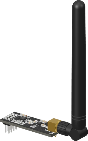
The nRF24L01+ PA+LNA is a 2.4 GHz SPI radio module: Nordic's nRF24L01+ (1.9 V to 3.6 V, 0 dBm maximum, 250 kbps to 2 Mbps) feeding a Skyworks RFX2401C front end that adds up to +22 dBm of output power and draws 90 mA at +20 dBm (Nordic nRF24L01+ product specification v1.0, p. 8; Skyworks RFX2401C datasheet, p. 4). Wire VCC to 3.3 V, never 5 V, with a 10 µF capacitor across VCC and GND at the module, then SCK, MOSI and MISO to the board's hardware SPI pins and CE and CSN to any two outputs. Its signal inputs are 5 V tolerant when VCC stays between 2.7 V and 3.3 V (p. 13).
The nRF24L01+ PA+LNA module pairs Nordic Semiconductor's nRF24L01+ single-chip 2.4 GHz transceiver with a Skyworks (formerly RFaxis) RFX2401C front-end chip and an SMA rubber-duck antenna. The nRF24L01+ handles the radio protocol, packets and acknowledgements; the RFX2401C boosts the outgoing signal with its power amplifier and lifts weak incoming signals with its low-noise amplifier. It is the long-range version of the familiar green nRF24L01+ board with a printed antenna.
The radio works on 126 channels between 2.400 and 2.525 GHz at 250 kbps, 1 Mbps or 2 Mbps, with 1 to 32 byte payloads, six data pipes for star networks, and automatic acknowledgement and retransmission in Nordic's Enhanced ShockBurst (Nordic nRF24L01+ product specification v1.0, pp. 8, 15). The microcontroller talks to it over SPI at up to 10 Mbps plus a CE line that starts transmit or receive, and an active-low IRQ pin can flag sent, received and failed packets (pp. 8, 11). The usual Arduino driver is TMRh20's RF24 library.
The bare chip transmits at 0, -6, -12 or -18 dBm (p. 8). The RFX2401C adds 25 dB of small-signal gain and up to +22 dBm of saturated output on transmit, and 12 dB of gain at a 2.5 dB noise figure on receive (Skyworks RFX2401C datasheet, p. 4). That extra power has a cost: the amplifier alone draws 90 mA at +20 dBm (p. 4), so the module needs a stiff 3.3 V supply and a capacitor at its pins, and it is the most common reason these modules fail when wired to a small board's 3.3 V pin.
nRF24L01+ PA+LNA pinout
| Pin | Function | Type |
|---|---|---|
| GND | GND (pin 1, square pad) | power in |
| VCC | VCC (3.3 V only)1.9–3.3 V | power in |
| CE | Digital | input |
| CSN | SPI CS | input |
| SCK | SPI SCK | input |
| MOSI | SPI MOSI | input |
| MISO | SPI MISO | output |
| IRQ | Digital | output |
How to wire the nRF24L01+ PA+LNA
Pin by pin, for the board you have.
| nRF24L01+ PA+LNA | Arduino Uno | Note |
|---|---|---|
| VCC | 3V3 | |
| GND | GND | |
| CE | D9 | |
| CSN | D10 | |
| SCK | D13 | |
| MOSI | D11 | |
| MISO | D12 |
- The PA+LNA board's amplifier draws more in transmit than the Uno's 3.3V pin is rated to supply (50 mA). Power it from its own 3.3 V regulator (an AMS1117-3.3 fed from 5V), put a 10 µF capacitor across VCC and GND at the module, and join the grounds.
| nRF24L01+ PA+LNA | ESP32 DevKit V1 | Note |
|---|---|---|
| VCC | 3V3 | |
| GND | GND | |
| CE | GPIO13 (D13) | |
| CSN | GPIO14 (D14) | |
| SCK | GPIO18 (D18) | |
| MOSI | GPIO23 (D23) | |
| MISO | GPIO19 (D19) |
| nRF24L01+ PA+LNA | Raspberry Pi Pico | Note |
|---|---|---|
| VCC | 3V3 | |
| GND | GND | |
| CE | GP0 | |
| CSN | GP1 | |
| SCK | GP18 | |
| MOSI | GP19 | |
| MISO | GP16 |
nRF24L01+ PA+LNA code
Every example here compiles for its board.
// nRF24L01+ PA+LNA on Arduino Uno: wiring and a free simulation at https://www.tinkered.ai/components/nrf24l01-pa-lna
#include <SPI.h>
#include <RF24.h>

RF24 radio(9, 10);                       // CE, CSN
uint8_t address[][6] = {"1Node", "2Node"};
float payload = 0.0;

void setup() {
  Serial.begin(115200);
  if (!radio.begin()) {
    Serial.println("radio hardware is not responding");
    while (true) delay(1000);
  }
  radio.setPALevel(RF24_PA_LOW);
  radio.setPayloadSize(sizeof(payload));  // 4 bytes, the same on both ends
  radio.openWritingPipe(address[0]);      // send to "1Node"
  radio.openReadingPipe(1, address[1]);   // listen on "2Node"
  radio.stopListening();                  // transmitter
}

void loop() {
  bool ok = radio.write(&payload, sizeof(payload));
  Serial.print(ok ? "sent " : "failed ");
  Serial.println(payload);
  payload += 0.01;
  delay(1000);
}
Before you wire it
- VCC to the board's 3.3 V pin (3V3) on every board, GND to GND. Add a 10 µF capacitor across VCC and GND, essential on a Nano.
- SCK, MOSI, MISO on the board's hardware SPI (table below); CE and CSN on free outputs, passed to RF24 radio(CE, CSN).
- TMRh20's RF24: #include <SPI.h>, #include <RF24.h>. Check radio.begin() and stop with a message if it fails.
- Both ends share the address bytes, channel, data rate and payload size (or both enableDynamicPayloads()). RF24's examples use the addresses "1Node" and "2Node", channel 76, 1 Mbps.
- radio.setPALevel(RF24_PA_LOW) on a desk; write() returns false after the retries run out (no acknowledgement), so print its result.
- No 5 V on VCC: it destroys the module.
- No RF24_PA_MAX from a Nano's 3.3 V pin without the capacitor.
- No CE or CSN on an ESP32's input-only pins (GPIO 34-39).
- No sharing MISO with a Catalex microSD module (its buffer never releases MISO).
- Power VCC from a 3.3 V rail and share ground with the board. The module has no regulator, and both chips are rated to 3.6 V at most (Nordic product specification, p. 13; Skyworks RFX2401C datasheet, p. 3), so 5 V on VCC destroys it.
- Solder or plug a 10 µF capacitor across VCC and GND right at the module's header. The amplifier pulls 90 mA at +20 dBm (Skyworks datasheet, p. 4) in short bursts, and a weak 3.3 V pin sags under them, which resets the radio mid-packet.
- On a 5 V board the SPI, CE and CSN lines can be wired straight in: the nRF24L01+ inputs are 5 V tolerant as long as its VDD stays between 2.7 V and 3.3 V (Nordic product specification, p. 13). MISO and IRQ swing only to 3.3 V, which a 5 V AVR reads as high.
- Wire SCK, MOSI and MISO to the board's hardware SPI pins and CE and CSN to any free outputs. IRQ is optional; RF24 polls the status register over SPI unless you want interrupts.
- On a desk, call radio.setPALevel(RF24_PA_LOW). Two amplified modules side by side at full power can overload each other's receivers, and low power also keeps the supply current down while you test.
- Its signal pins are 5 V tolerant only while VDD is 2.7 to 3.3 V.
Specifications
- Supply voltage
- nRF24L01+ 1.9 V to 3.6 V (3.0 V typical); RFX2401C 2.0 V to 3.6 V; feed the module 3.3 VNordic nRF24L01+ product specification v1.0, p. 13; Skyworks RFX2401C datasheet 204359C, p. 3
- 5 V tolerant inputs
- Yes, when VDD is 2.7 V to 3.3 VNordic nRF24L01+ product specification v1.0, pp. 8, 13
- Frequency and channels
- 2.400 to 2.525 GHz, 126 RF channelsNordic nRF24L01+ product specification v1.0, pp. 8, 15
- Air data rate
- 250 kbps, 1 Mbps or 2 MbpsNordic nRF24L01+ product specification v1.0, p. 8
- Chip output power
- 0, -6, -12 or -18 dBm (programmable)Nordic nRF24L01+ product specification v1.0, p. 8
- Front-end output power
- Up to +22 dBm saturated, 25 dB small-signal gainSkyworks RFX2401C datasheet 204359C, p. 4
- Receive
- Chip sensitivity -94 dBm at 250 kbps, -82 dBm at 2 Mbps; LNA adds 12 dB gain at 2.5 dB noise figureNordic nRF24L01+ product specification v1.0, p. 8; Skyworks RFX2401C datasheet, p. 4
- Current
- Chip 11.3 mA TX at 0 dBm, 13.5 mA RX at 2 Mbps, 900 nA power down; amplifier 90 mA at +20 dBm outNordic nRF24L01+ product specification v1.0, p. 8; Skyworks RFX2401C datasheet, p. 4
- Packets
- 1 to 32 byte payload, 6 data pipes, three 32-byte TX and RX FIFOsNordic nRF24L01+ product specification v1.0, p. 8
- SPI
- Up to 10 Mbps; CE starts TX or RX; IRQ active lowNordic nRF24L01+ product specification v1.0, pp. 8, 11
- Maximum supply voltage
- 3.6 V
- Interface
- SPI
- Dimensions
- 61.95 × 15.5 × 113.1 mm
- Weight
- 14 g
From the Nordic nRF24L01+ / RFX2401C (generic PA+LNA module)'s datasheet, published by Nordic nRF24L01+ / RFX2401C (generic PA+LNA module).
Common mistakes
Powering it from 5 V
VCC is rated 1.9 V to 3.6 V for the nRF24L01+ and 2.0 V to 3.6 V for the RFX2401C (Nordic product specification, p. 13; Skyworks datasheet, p. 3). There is no regulator on the module, so 5 V on VCC kills it. Use the board's 3V3 pin or a 3.3 V regulator.
No capacitor on a weak 3.3 V pin
At high power the amplifier alone takes 90 mA (Skyworks RFX2401C datasheet, p. 4). Small boards whose 3.3 V pin cannot supply that brown the module out: begin() succeeds but write() fails or the sketch hangs. Put 10 µF across VCC and GND at the module, or use an nRF24 adapter board with its own regulator.
Mismatched settings between the two ends
Both radios must share the address, channel, data rate and payload size, or both enable dynamic payloads. A mismatch looks like a dead radio: write() returns false once the retries run out because no acknowledgement arrives.
Testing at full power at arm's length
Two PA+LNA modules a few centimetres apart at RF24_PA_MAX can saturate each other's receivers, so packets drop even though the wiring is fine. Use RF24_PA_LOW on a desk and raise the level once the boards are far apart.
Running without the antenna
The amplifier is designed to drive a 50 Ω antenna port (Skyworks RFX2401C datasheet, p. 4). Screw the SMA antenna on before transmitting; with it missing, range collapses and the output stage works into a badly mismatched load.
nRF24L01+ PA+LNA questions
Can I connect the nRF24L01+ PA+LNA to a 5 V Arduino?
Yes, with VCC on the Arduino's 3.3 V pin, never 5 V. The data pins can go straight to the Uno's D9 to D13 because the nRF24L01+ inputs are 5 V tolerant while VDD is 2.7 V to 3.3 V (Nordic nRF24L01+ product specification v1.0, p. 13). Add a 10 µF capacitor across VCC and GND at the module.
What is the difference between the nRF24L01+ PA+LNA and the plain nRF24L01+ module?
Both use the same nRF24L01+ chip and code. The plain module transmits at 0 dBm at most from a printed antenna (Nordic product specification, p. 8); the PA+LNA adds an RFX2401C front end with up to +22 dBm output and a low-noise amplifier with 12 dB gain on receive, plus an SMA antenna (Skyworks RFX2401C datasheet, p. 4). The price is current: about 90 mA for the amplifier at +20 dBm against 11.3 mA for the bare chip at 0 dBm.
Why does radio.write() always return false?
write() returns false when no acknowledgement came back after all retries. Check that the receiver is powered and listening, that both ends share address, channel, data rate and payload size, that VCC has its 10 µF capacitor, and that the two modules are not side by side at RF24_PA_MAX. If radio.begin() itself fails, recheck the SPI wiring and the CE and CSN pin numbers.
How much current does the nRF24L01+ PA+LNA draw?
The nRF24L01+ itself draws 11.3 mA transmitting at 0 dBm and 13.5 mA receiving at 2 Mbps (Nordic product specification, p. 8). The RFX2401C amplifier draws 17 mA idle in transmit and 90 mA at +20 dBm output (Skyworks datasheet, p. 4), so budget about 100 mA of transmit bursts on the 3.3 V rail.
Can I use the nRF24L01+ PA+LNA with an ESP32 or Raspberry Pi Pico?
Yes. Both are 3.3 V boards, so every pin wires directly: VCC to 3V3, SCK, MOSI and MISO to the hardware SPI pins (GPIO18, 23 and 19 on a classic ESP32), and CE and CSN to free outputs. On an ESP32 avoid GPIO34 to 39 for CE and CSN, since those pins are input only.
Which data rate gives the longest range?
250 kbps. The nRF24L01+ receiver is most sensitive there, -94 dBm against -85 dBm at 1 Mbps and -82 dBm at 2 Mbps (Nordic product specification, p. 8), so set radio.setDataRate(RF24_250KBPS) on both ends for distance.
Build something with the nRF24L01+ PA+LNA
- Build this
Long-range RC transmitter and receiver
Send joystick positions from a handheld Arduino to a car, boat or plane, with ACK payloads carrying battery voltage back.
- Build this
Remote weather station
A battery node in the garden sends temperature and humidity to an indoor display, sleeping in power down between readings.
- Build this
Star sensor network
Use the six data pipes so one hub collects readings from up to six nodes on separate addresses.
- Build this
Wireless doorbell or mailbox alert
A button or reed switch wakes a sender that signals a receiver in the house across walls and floors.
This page as plain Markdown, for ChatGPT, Claude or your own agent. /components/nrf24l01-pa-lna.md