DRV8871
A single H-bridge breakout for one brushed DC motor at 6.5 V to 45 V, 3.6 A peak, with current limiting set by one resistor and two PWM inputs.
- Motor supply (VM)6.5 V to 45 V
- Peak output current3.6 A
- On-resistance565 mOhm typical (high side + low side)
- Logic inputsHigh from 1.5 V, low below 0.5 V; 0 V to 5.5 V recommended, 7 V absolute maximum; 100 kOhm pull-downs
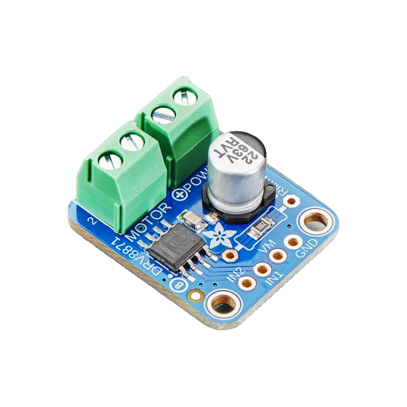
The DRV8871 drives one brushed DC motor from 6.5 V to 45 V with up to 3.6 A peak, controlled by two inputs, IN1 and IN2, that read 3.3 V or 5 V logic (TI DRV8871 datasheet SLVSCY9B, pp. 1, 4, 5). It limits current without a sense resistor: I_TRIP = 64 kV / R_ILIM, and Adafruit's breakout fits 30 kOhm for about 2 A (Adafruit #3190 product page). Both inputs low lets the motor coast and puts the chip to sleep after about 1 ms (datasheet, pp. 5, 8).
The DRV8871 is a single H-bridge made of N-channel MOSFETs with 565 mOhm total on-resistance (TI datasheet, p. 1), packed with protection: undervoltage lockout, overcurrent shutdown with automatic retry every 3 ms, and thermal shutdown at 150 °C (pp. 5, 10). It suits 12 V and 24 V gear motors, pumps and linear actuators that an L298N would struggle with.
Its party trick is current regulation without a shunt: a resistor from ILIM to ground sets the chopping current, I_TRIP = 64 kV / R_ILIM, so 32 kOhm limits the motor to 2 A however hard it is loaded (datasheet, p. 9). Adafruit's breakout ships with 30 kOhm, about 2 A (Adafruit #3190), which keeps stalls and start-ups from tripping your supply.
There is no logic supply pin: IN1 and IN2 read high from 1.5 V and accept up to 5.5 V (datasheet, pp. 4, 5), so any 3.3 V or 5 V board drives it. Holding one input high and pulsing the other gives brake/slow-decay PWM, the mode TI recommends for speed control (p. 10).
DRV8871 pinout
| Pin | Function | Type |
|---|---|---|
| IN1 | PWM3.3 V or 5 V logic | input |
| IN2 | PWM3.3 V or 5 V logic | input |
| VM | VM6.5 V to 45 V | power in |
| GND | GND | power in |
| POWER_PLUS | POWER +6.5 V to 45 V | power in |
| POWER_MINUS | POWER - | power in |
| OUT1 | Motor | output |
| OUT2 | Motor | output |
How to wire the DRV8871
Pin by pin, for the board you have.
| DRV8871 | Arduino Uno | Note |
|---|---|---|
| IN1 | D9 | |
| IN2 | D10 | |
| GND | GND | |
| POWER_PLUS | 12 V supply + | |
| POWER_MINUS | 12 V supply - | |
| OUT1 | Motor | |
| OUT2 | Motor |
- The motor supply goes to the POWER terminal only, never to the Uno. The GND header pin joins the two grounds.
- Choose a supply that can deliver the 2 A the breakout allows, or more if you change R_ILIM.
| DRV8871 | ESP32 DevKit V1 | Note |
|---|---|---|
| IN1 | GPIO25 (D25) | |
| IN2 | GPIO26 (D26) | |
| GND | GND | |
| POWER_PLUS | 12 V supply + | |
| POWER_MINUS | 12 V supply - | |
| OUT1 | Motor | |
| OUT2 | Motor |
- IN1 and IN2 read 3.3 V as high (1.5 V threshold); nothing from the motor side reaches the ESP32's pins.
- Keep VM and the POWER terminal away from VIN; only GND is shared.
| DRV8871 | Raspberry Pi Pico | Note |
|---|---|---|
| IN1 | GP6 | |
| IN2 | GP7 | |
| GND | GND | |
| POWER_PLUS | 12 V supply + | |
| POWER_MINUS | 12 V supply - | |
| OUT1 | Motor | |
| OUT2 | Motor |
- The motor supply must never reach VSYS or VBUS; share only GND with the Pico.
DRV8871 code
Every example here compiles for its board.
// DRV8871 on Arduino Uno: wiring and a free simulation at https://www.tinkered.ai/components/drv8871
// DRV8871 on an Arduino Uno: IN1 D9, IN2 D10. Brake/slow-decay PWM as TI recommends:
// one input held HIGH, the other pulsed. speed -255..255, 0 = coast (driver sleeps after 1 ms).
const int IN1 = 9, IN2 = 10;

void setMotor(int speed) {
  speed = constrain(speed, -255, 255);
  if (speed > 0) {          // forward: IN1 high, PWM IN2 (low part of the cycle drives)
    digitalWrite(IN1, HIGH);
    analogWrite(IN2, 255 - speed);
  } else if (speed < 0) {   // reverse: IN2 high, PWM IN1
    digitalWrite(IN2, HIGH);
    analogWrite(IN1, 255 + speed);
  } else {                  // coast
    digitalWrite(IN1, LOW);
    digitalWrite(IN2, LOW);
  }
}

void setup() {
  Serial.begin(115200);
  pinMode(IN1, OUTPUT);
  pinMode(IN2, OUTPUT);
  setMotor(0);
  Serial.println("DRV8871 ready");
}

void loop() {
  for (int s = 0; s <= 255; s += 51) { setMotor(s); Serial.print("Speed "); Serial.println(s); delay(800); }
  setMotor(0); Serial.println("Coast"); delay(1500);
  for (int s = 0; s >= -255; s -= 51) { setMotor(s); Serial.print("Speed "); Serial.println(s); delay(800); }
  setMotor(0); Serial.println("Coast"); delay(1500);
}
// DRV8871 on ESP32 DevKit V1: wiring and a free simulation at https://www.tinkered.ai/components/drv8871
// DRV8871 on an ESP32 DevKit V1: IN1 GPIO25, IN2 GPIO26. Fast-decay PWM at the core's default 1 kHz,
// so the off time stays under the chip's 1 ms sleep timer. speed -255..255, 0 = coast.
const int IN1 = 25, IN2 = 26;

void setMotor(int speed) {
  speed = constrain(speed, -255, 255);
  if (speed > 0) {          // forward: PWM IN1, IN2 low (fast decay)
    analogWrite(IN1, speed);
    analogWrite(IN2, 0);
  } else if (speed < 0) {   // reverse: PWM IN2, IN1 low
    analogWrite(IN1, 0);
    analogWrite(IN2, -speed);
  } else {                  // coast
    analogWrite(IN1, 0);
    analogWrite(IN2, 0);
  }
}

void setup() {
  Serial.begin(115200);
  pinMode(IN1, OUTPUT);
  pinMode(IN2, OUTPUT);
  setMotor(0);
  Serial.println("DRV8871 ready");
}

void loop() {
  for (int s = 0; s <= 255; s += 51) { setMotor(s); Serial.printf("Speed %d\n", s); delay(800); }
  setMotor(0); Serial.println("Coast"); delay(1500);
  for (int s = 0; s >= -255; s -= 51) { setMotor(s); Serial.printf("Speed %d\n", s); delay(800); }
  setMotor(0); Serial.println("Coast"); delay(1500);
}
// DRV8871 on Raspberry Pi Pico: wiring and a free simulation at https://www.tinkered.ai/components/drv8871
// DRV8871 on a Raspberry Pi Pico (arduino-pico): IN1 GP6, IN2 GP7. Fast-decay PWM at 20 kHz,
// so the off time stays far under the chip's 1 ms sleep timer. speed -255..255, 0 = coast.
const int IN1 = 6, IN2 = 7;

void setMotor(int speed) {
  speed = constrain(speed, -255, 255);
  if (speed > 0) {          // forward: PWM IN1, IN2 low (fast decay)
    analogWrite(IN1, speed);
    analogWrite(IN2, 0);
  } else if (speed < 0) {   // reverse: PWM IN2, IN1 low
    analogWrite(IN1, 0);
    analogWrite(IN2, -speed);
  } else {                  // coast
    analogWrite(IN1, 0);
    analogWrite(IN2, 0);
  }
}

void setup() {
  Serial.begin(115200);
  analogWriteFreq(20000);
  analogWriteRange(255);
  pinMode(IN1, OUTPUT);
  pinMode(IN2, OUTPUT);
  setMotor(0);
  Serial.println("DRV8871 ready");
}

void loop() {
  for (int s = 0; s <= 255; s += 51) { setMotor(s); Serial.print("Speed "); Serial.println(s); delay(800); }
  setMotor(0); Serial.println("Coast"); delay(1500);
  for (int s = 0; s >= -255; s -= 51) { setMotor(s); Serial.print("Speed "); Serial.println(s); delay(800); }
  setMotor(0); Serial.println("Coast"); delay(1500);
}
Before you wire it
- Keep VM between 6.5 V and 45 V (TI datasheet, p. 4), with headroom for the voltage a motor pumps back when it brakes.
- Join the motor supply's ground and your board's GND through the breakout's GND pin.
- Size R_ILIM for your motor: I_TRIP = 64 kV / R_ILIM, never below 15 kOhm (datasheet, p. 9).
- Keep the PWM off time shorter than the 1 ms sleep timer (datasheet, p. 5): use slow decay (one input high, the other pulsed, as TI suggests on p. 10) or fast decay at 1 kHz or more.
- Never drive the inputs above 5.5 V; 7 V is the absolute maximum (datasheet, pp. 3, 4).
- Never power the motor from your board's 5V pin; VM needs at least 6.5 V anyway.
- Never count on more than 3.6 A, and only for a few hundred milliseconds even with R_ILIM at 15 kOhm (datasheet, p. 10).
- Never wire VM header and POWER terminal to two different supplies: they are the same net.
- Truth table: IN1/IN2 = 0/0 coast (and sleep after about 1 ms), 0/1 reverse, 1/0 forward, 1/1 brake (TI datasheet, p. 8).
- Current regulation chops the bridge whenever the motor current reaches I_TRIP, so a stalled motor is held at the limit instead of drawing its full stall current (datasheet, p. 10).
- Overcurrent above 3.7 A to 6.4 A shuts the bridge for 3 ms and then retries; thermal shutdown at 150 °C clears itself once the die cools (datasheet, pp. 5, 10).
- On the Uno, D9 and D10 run PWM at about 490 Hz, so the sketch holds one input high and pulses the other (slow decay) to keep both inputs from sitting low past the 1 ms sleep timer. The ESP32 and Pico sketches use fast decay at 1 kHz and 20 kHz, where the off time stays shorter.
- PWM up to 200 kHz is allowed, but at that frequency only 16 % to 84 % duty is usable (datasheet, p. 4).
Specifications
- Motor supply (VM)
- 6.5 V to 45 VTI DRV8871 datasheet SLVSCY9B, p. 4
- Peak output current
- 3.6 ATI DRV8871 datasheet SLVSCY9B, p. 4
- On-resistance
- 565 mOhm typical (high side + low side)TI DRV8871 datasheet SLVSCY9B, p. 1
- Logic inputs
- High from 1.5 V, low below 0.5 V; 0 V to 5.5 V recommended, 7 V absolute maximum; 100 kOhm pull-downsTI DRV8871 datasheet SLVSCY9B, pp. 3, 4, 5
- Input PWM frequency
- Up to 200 kHzTI DRV8871 datasheet SLVSCY9B, p. 4
- Current limit
- I_TRIP = 64 kV / R_ILIM; R_ILIM at least 15 kOhmTI DRV8871 datasheet SLVSCY9B, p. 9
- Breakout current limit
- 30 kOhm fitted, about 2 AAdafruit DRV8871 DC Motor Driver Breakout (#3190) product page
- Overcurrent trip
- 3.7 A minimum, 4.5 A typical; retry after 3 msTI DRV8871 datasheet SLVSCY9B, p. 5
- Sleep
- Both inputs low for 1 ms to 1.5 ms; 10 µA at 12 VTI DRV8871 datasheet SLVSCY9B, p. 5
From the DRV8871 3.6-A Brushed DC Motor Driver With Internal Current Sense, SLVSCY9B (revised July 2016), published by Texas Instruments.
Common mistakes
Fast-decay PWM with long low periods
Pulsing IN1 while IN2 stays low leaves both inputs low during the off time. At low duty and low PWM frequency that can exceed the 1 ms sleep timer (datasheet, p. 5) and make low speeds stutter. Hold one input high and pulse the other instead.
Motor too weak at start
The breakout's 30 kOhm limits current to about 2 A (Adafruit #3190). A big motor that needs more to start just hums. Lower R_ILIM, but never below 15 kOhm (datasheet, p. 9).
Running a 5 V motor from 5 V
The DRV8871 needs 6.5 V or more on VM (datasheet, p. 4). For 3 V to 6 V hobby motors use a DRV8833 or TB6612FNG.
Ignoring regenerative voltage
A braking motor feeds energy back into VM. With a 45 V maximum and a 24 V supply this is rarely a problem, but a bench supply with no capacitor near the board can see spikes; keep the breakout's bulk capacitor and add more for big motors.
DRV8871 questions
DRV8871 vs L298N: which is better?
For one motor, the DRV8871: its MOSFET bridge has 565 mOhm total on-resistance (TI datasheet, p. 1), built-in current limiting and protection, and it runs to 45 V. The L298N drives two motors but loses far more voltage in its bipolar outputs and has no current regulation.
How do I set the DRV8871 current limit?
With the resistor on ILIM: I_TRIP = 64 kV / R_ILIM, so 32 kOhm gives 2 A and 15 kOhm, the minimum, about 4.3 A (TI datasheet, p. 9). Adafruit fits 30 kOhm for about 2 A.
Does the DRV8871 work with a 3.3 V ESP32 or Pico?
Yes. IN1 and IN2 read high from 1.5 V (datasheet, p. 5), and the breakout has no logic supply to match. Wire the inputs straight to GPIOs and share ground.
Can the DRV8871 drive two motors?
No, it has one H-bridge. Use two breakouts, or a dual driver such as the TB6612FNG or DRV8833 for smaller motors.
Why does my motor stop for a moment under load?
The overcurrent protection: above 3.7 A to 6.4 A the bridge turns off for 3 ms and retries (datasheet, pp. 5, 10). Reduce the load, add current limiting with a higher R_ILIM, or use a larger driver.
Build something with the DRV8871
- Build this
Linear actuator controller
Extend and retract a 12 V actuator with buttons.
- Build this
Motorized curtain
Open and close curtains with a geared 24 V motor and limit switches.
- Build this
Peristaltic pump dosing
Dose liquid by running a pump for timed intervals.
This page as plain Markdown, for ChatGPT, Claude or your own agent. /components/drv8871.md