HW-038 Water Level Sensor
A cheap analog water sensor whose output voltage rises as more of its exposed traces go under water.
- Supply3.3 V to 5 V
- OutputAnalog on S: 0 V dry, rising with the wetted length
- Sensing traces10 interleaved: 5 to + through 100 Ω, 5 to the transistor's base
- TransistorS8050 NPN, emitter on S with 100 Ω to ground
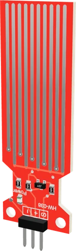
The HW-038 is a 3.3 V to 5 V water level sensor: ten interleaved copper traces feed an S8050 transistor, so its S pin outputs 0 V when dry and an analog voltage that rises as more of the traces are wet (Last Minute Engineers HW-038 teardown). Wire S to an analog input, - to GND and + to a digital pin you switch on only while reading, which slows the electrolytic corrosion of the traces.
The HW-038 is a small red board with a sensing area of exposed, interleaved copper traces, a three-pin header labelled S, + and -, an S8050 NPN transistor and a power LED. It is sold as a water level, water detection or rain sensor and used in leak alarms, tank monitors and plant watering projects with an Arduino, ESP32 or Raspberry Pi Pico.
Of its ten traces, five connect to + through a 100 Ω resistor and five connect to the base of the S8050; the transistor's emitter is the S pin, with 100 Ω to ground (Last Minute Engineers HW-038 teardown). Dry, nothing reaches the base and S reads 0 V. Water bridging the two sets of traces acts as the base resistor, so the more of the traces are under water, the more current flows and the higher S rises. The output is analog and proportional to the immersed length, not a calibrated depth.
Two things limit it. The reading depends on the water as much as on the depth: minerals and salt make water conduct better, so the same level reads differently in tap, rain or salt water, and the response flattens as the water rises. And DC across wet copper corrodes the traces over time, which is why the common wiring powers + from a digital pin only for the instant of each reading. The board is meant to be dipped only up to its traces, not fully submerged.
HW-038 Water Level Sensor pinout
| Pin | Function | Type |
|---|---|---|
| S | ADC rises with the water level, 0 V dry | output |
| VCC | + (3-5 V)3–5 V | power in |
| GND | − (GND) | power in |
How to wire the HW-038 Water Level Sensor
Pin by pin, for the board you have.
| HW-038 Water Level Sensor | Arduino Uno | Note |
|---|---|---|
| VCC | D7 | |
| GND | GND | |
| S | A0 |
- The module pulls S to GND through only 100 Ω, so in very conductive (salty) water + can draw tens of milliamps from the pin that powers it. An Uno pin is rated 20 mA (40 mA absolute maximum): for salt water, switch + through a transistor.
| HW-038 Water Level Sensor | ESP32 DevKit V1 | Note |
|---|---|---|
| VCC | GPIO13 (D13) | |
| GND | GND | |
| S | GPIO33 (D33) |
- The module pulls S to GND through only 100 Ω, so in very conductive (salty) water + can draw tens of milliamps from the pin that powers it. For salt water, switch + through a transistor rather than straight from GPIO13.
| HW-038 Water Level Sensor | Raspberry Pi Pico | Note |
|---|---|---|
| VCC | GP0 | |
| GND | GND | |
| S | GP28 |
- The module pulls S to GND through only 100 Ω, so in very conductive (salty) water + can draw tens of milliamps from the pin that powers it. An RP2040 pin gives 12 mA at most (the sketch sets that drive; the default is 4 mA): for salt water, switch + through a transistor.
HW-038 Water Level Sensor code
Every example here compiles for its board.
// HW-038 Water Level Sensor on Arduino Uno: wiring and a free simulation at https://www.tinkered.ai/components/water-level-sensor-hw-038
const int POWER_PIN = 7;    // HW-038 +: powered only to read (the traces corrode under constant DC)
const int SIGNAL_PIN = A0;  // HW-038 S
const int DRY_BELOW = 100;  // under this the traces are dry

// what this sensor reads in this water at 0, 25, 50, 75 and 100 % of its sensing length (tap water, 5 V)
const int CAL[5] = { 335, 487, 565, 611, 641 };

int readSensor() {
  digitalWrite(POWER_PIN, HIGH);
  delay(10);                       // let S settle
  int raw = analogRead(SIGNAL_PIN);
  digitalWrite(POWER_PIN, LOW);
  return raw;
}

int levelPercent(int raw) {
  if (raw < DRY_BELOW) return 0;
  if (raw <= CAL[0]) return 1;
  for (int i = 1; i < 5; i++) {
    if (raw <= CAL[i]) return 25 * (i - 1) + (long)(raw - CAL[i - 1]) * 25 / (CAL[i] - CAL[i - 1]);
  }
  return 100;
}

void setup() {
  Serial.begin(9600);
  pinMode(POWER_PIN, OUTPUT);
  digitalWrite(POWER_PIN, LOW);
  Serial.println("HW-038 ready");
}

void loop() {
  int raw = readSensor();
  Serial.print("raw ");
  Serial.print(raw);
  Serial.print("  level ");
  Serial.print(levelPercent(raw));
  Serial.println(" %");
  delay(1000);
}
// HW-038 Water Level Sensor on ESP32 DevKit V1: wiring and a free simulation at https://www.tinkered.ai/components/water-level-sensor-hw-038
const int POWER_PIN = 13;    // HW-038 +: powered only to read (the traces corrode under constant DC)
const int SIGNAL_PIN = 33;   // HW-038 S
const int DRY_BELOW_MV = 320;  // under this the traces are dry

// S in millivolts at 0, 25, 50, 75 and 100 % of the sensing length. These starting points are
// a 5 V tap-water calibration scaled to the 3.3 V that + gets here: S depends on the water and
// on the sensor, so record your own at known levels and replace them.
const int CAL_MV[5] = { 1080, 1570, 1820, 1970, 2070 };

int readMilliVolts() {
  digitalWrite(POWER_PIN, HIGH);
  delay(10);                                    // let S settle
  int mv = analogReadMilliVolts(SIGNAL_PIN);    // calibrated: the ESP32's raw 12-bit reading is not linear
  digitalWrite(POWER_PIN, LOW);
  return mv;
}

int levelPercent(int mv) {
  if (mv < DRY_BELOW_MV) return 0;
  if (mv <= CAL_MV[0]) return 1;
  for (int i = 1; i < 5; i++) {
    if (mv <= CAL_MV[i]) return 25 * (i - 1) + (long)(mv - CAL_MV[i - 1]) * 25 / (CAL_MV[i] - CAL_MV[i - 1]);
  }
  return 100;
}

void setup() {
  Serial.begin(9600);
  pinMode(POWER_PIN, OUTPUT);
  digitalWrite(POWER_PIN, LOW);
  analogSetPinAttenuation(SIGNAL_PIN, ADC_11db);   // 11 dB, the widest range: Espressif rates it accurate to about 2.45 V
  Serial.println("HW-038 ready");
}

void loop() {
  int mv = readMilliVolts();
  Serial.print("S ");
  Serial.print(mv);
  Serial.print(" mV  level ");
  Serial.print(levelPercent(mv));
  Serial.println(" %");
  delay(1000);
}
// HW-038 Water Level Sensor on Raspberry Pi Pico: wiring and a free simulation at https://www.tinkered.ai/components/water-level-sensor-hw-038
#include <hardware/gpio.h>

const int POWER_PIN = 0;    // HW-038 + on GP0: powered only to read (the traces corrode under constant DC)
const int SIGNAL_PIN = 28;  // HW-038 S on GP28 (ADC2)
const int DRY_BELOW = 100;  // under this the traces are dry

// 10-bit counts (arduino-pico's default) at 0, 25, 50, 75 and 100 % of the sensing length.
// + and the ADC reference are both 3.3 V here, so these tap-water figures from a 5 V Uno
// (both on 5 V) are a starting point only: record your own at known levels.
const int CAL[5] = { 335, 487, 565, 611, 641 };

int readSensor() {
  digitalWrite(POWER_PIN, HIGH);
  delay(10);                       // let S settle
  int raw = analogRead(SIGNAL_PIN);
  digitalWrite(POWER_PIN, LOW);
  return raw;
}

int levelPercent(int raw) {
  if (raw < DRY_BELOW) return 0;
  if (raw <= CAL[0]) return 1;
  for (int i = 1; i < 5; i++) {
    if (raw <= CAL[i]) return 25 * (i - 1) + (long)(raw - CAL[i - 1]) * 25 / (CAL[i] - CAL[i - 1]);
  }
  return 100;
}

void setup() {
  Serial.begin(9600);
  pinMode(POWER_PIN, OUTPUT);
  digitalWrite(POWER_PIN, LOW);
  gpio_set_drive_strength(POWER_PIN, GPIO_DRIVE_STRENGTH_12MA);   // the RP2040's default is 4 mA
  Serial.println("HW-038 ready");
}

void loop() {
  int raw = readSensor();
  Serial.print("raw ");
  Serial.print(raw);
  Serial.print("  level ");
  Serial.print(levelPercent(raw));
  Serial.println(" %");
  delay(1000);
}
Before you wire it
- + (VCC) either to a GPIO the sketch drives HIGH only while reading (preferred: it stops the corrosion), or to the board's 5 V (Uno, Nano, Mega, UNO R4) / 3V3 (ESP32, ESP32-S3, ESP32-C3, ESP8266, Pico). − (GND) to GND.
- S to an ANALOG input: A0-A5 on an Uno, Nano or UNO R4, A0-A15 on a Mega, GP26-GP28 on a Pico, A0 on an ESP8266 NodeMCU, an ADC1 pin on an ESP32 (GPIO32-39; GPIO0-4 on a C3, GPIO1-10 on an S3).
- Powered from a GPIO: pinMode(POWER_PIN, OUTPUT), then for each reading digitalWrite(POWER_PIN, HIGH); delay(10); analogRead(S); digitalWrite(POWER_PIN, LOW);.
- Turn readings into a level with a calibration table (the readings at 0, 25, 50, 75 and 100 %) and interpolate between its points; never with map() over one straight line.
- Anything under about 100 counts (10 bits) is dry.
- No digitalRead() on S: it is analog (on 5 V it reads HIGH only near full immersion).
- No more than 5 V on +, and NO 5 V on + with a 3.3 V board (S would pass 3.3 V in salt water).
- No leaving + on 5 V for hours while the board sits in water: power it only to read.
- No ESP32 ADC2 pin (GPIO 0/2/4/12-15/25-27) for S when the sketch uses Wi-Fi. GPIO5 on an ESP32-C3 is ADC2: the Arduino core refuses analogRead there.
- Do not promise millimetre accuracy or a linear depth reading: the output flattens as the water rises and drifts with the water's minerals.
- Read S with an analog input: A0 to A5 on an Uno or Nano, GP26 to GP28 on a Pico, A0 on an ESP8266 NodeMCU, an ADC1 pin on an ESP32. ADC2 pins on an ESP32 cannot be read while Wi-Fi is running.
- Power + from a digital pin that you drive HIGH only to take a reading, wait a few milliseconds for S to settle, read, then drive it LOW. Continuous DC across wet traces corrodes them; powering the board only to read slows that down.
- Match the supply to the board's ADC. On a 3.3 V board (ESP32, ESP8266, Pico) power + from 3.3 V or a 3.3 V GPIO; never put 5 V on + with a 3.3 V board, because S can climb toward the supply in very conductive water.
- Calibrate in the water you will measure. Record the readings at a few known levels (empty, quarter, half, full) and interpolate between them; the response is not linear, so a single straight-line map() reads wrong at the top.
- Dip only the trace area. Keep the header, the transistor and the LED dry.
Specifications
- Supply
- 3.3 V to 5 VLast Minute Engineers HW-038 teardown
- Output
- Analog on S: 0 V dry, rising with the wetted lengthLast Minute Engineers HW-038 teardown
- Sensing traces
- 10 interleaved: 5 to + through 100 Ω, 5 to the transistor's baseLast Minute Engineers HW-038 teardown
- Transistor
- S8050 NPN, emitter on S with 100 Ω to groundLast Minute Engineers HW-038 teardown
- Indicator
- Power LED, lit whenever + is poweredLast Minute Engineers HW-038 teardown
- Pinout
- S (signal), + (VCC), - (GND)Board silkscreen
- Interface
- One analog input; no I2C, no digital thresholdLast Minute Engineers HW-038 teardown
- Supply voltage
- 3–5 V
- Maximum supply voltage
- 5.5 V
- Dimensions
- 20.2 × 4.2 × 65.3 mm
- Weight
- 3.5 g
From the Generic (HW-038)'s datasheet, published by Generic (HW-038).
Common mistakes
Leaving + permanently powered in water
DC across the wet traces drives electrolysis, and the copper corrodes over days or weeks, so readings drift downward and the board eventually stops working. Power + from a GPIO only while reading.
Reading S with digitalRead()
S is an analog voltage that rises gradually with the water level. A digital input only flips once that voltage crosses its logic threshold, so it misses everything but a nearly full immersion. Use analogRead().
Treating the output as a depth in millimetres
The voltage climbs steeply at first contact and flattens near the top, and it depends on how conductive the water is. Calibrate it in the actual water and treat it as a level indicator, not a ruler.
Powering + from a GPIO that is never turned on
When + is wired to a digital pin, the sketch must set that pin as an OUTPUT and drive it HIGH before analogRead(). Otherwise the board is unpowered and S always reads 0, which looks like a dead sensor.
Using it in distilled or very pure water
The sensor relies on the water conducting between its traces. Distilled water barely conducts, so the reading stays near zero even when the board is under water.
HW-038 Water Level Sensor questions
Can I use the HW-038 with a 3.3 V board like an ESP32 or Pico?
Yes. It runs from 3.3 V to 5 V (Last Minute Engineers HW-038 teardown). Power + from 3.3 V or a 3.3 V GPIO so S can never exceed the ADC's range, and on an ESP32 use an ADC1 pin, since ADC2 is unavailable while Wi-Fi is on.
Why does my water level sensor always read 0?
S reads 0 V whenever the traces are dry (Last Minute Engineers HW-038 teardown). If it stays at 0 in water, check that + actually has power (a GPIO feeding it must be driven HIGH before each read), that - shares the board's ground, that S goes to an analog pin, and that the water is not distilled.
How do I stop the HW-038 from corroding?
Power it only while reading: wire + to a digital pin, drive it HIGH, wait a few milliseconds, read S, then drive it LOW, and take readings seconds or minutes apart rather than continuously. Corrosion comes from DC across the wet traces, so less powered time means a longer life.
How do I convert the reading into a water level?
Calibrate it. Log the analog readings with the traces empty, a quarter, half and fully under the water you will measure, store them in a table and interpolate between the points. The response is non-linear and depends on the water's minerals, so values from another setup do not transfer.
Can the HW-038 be used as a rain or leak sensor?
Yes. Any water bridging its traces raises S above the dry 0 V reading, so a threshold slightly above the dry value detects a leak or rain drops. For rain on a roof, a dedicated rain board with a separate comparator is more robust, but the HW-038 works for leak alarms under a sink or a washing machine.
Build something with the HW-038 Water Level Sensor
- Build this
Leak alarm
Sound a buzzer or send a phone notification when water appears under a sink, boiler or washing machine.
- Build this
Tank or reservoir level indicator
Show an approximate fill level on LEDs or an OLED after calibrating in the tank's water.
- Build this
Automatic plant watering
Check the reservoir before running a pump so it never runs dry.
- Build this
Sump or flood warning
Log the level on an ESP32 and alert over Wi-Fi when it rises.
This page as plain Markdown, for ChatGPT, Claude or your own agent. /components/water-level-sensor-hw-038.md