HW-038 Water Level Sensor with an ESP32 DevKit V1
A cheap analog water sensor whose output voltage rises as more of its exposed traces go under water.
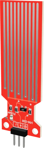
On the ESP32 DevKit V1 the HW-038's + comes from GPIO13, driven HIGH for 10 ms only when the sketch takes a reading, and its S output goes to GPIO33 on ADC1. With + at 3.3 V, S can never climb past the ESP32's input limit, and the sketch reads it in millivolts with analogReadMilliVolts(), so its level table is written in millivolts too.
Wiring the HW-038 Water Level Sensor to the ESP32 DevKit V1
Pin by pin.
| HW-038 Water Level Sensor | ESP32 DevKit V1 |
|---|---|
| VCC | GPIO13 (D13) |
| GND | GND |
| S | GPIO33 (D33) |
- The module pulls S to GND through only 100 Ω, so in very conductive (salty) water + can draw tens of milliamps from the pin that powers it. For salt water, switch + through a transistor rather than straight from GPIO13.
What to know on the ESP32 DevKit V1
- CAL_MV {1080, 1570, 1820, 1970, 2070} and DRY_BELOW_MV 320 were not measured on an ESP32: they are the Uno's 5 V tap-water counts turned into volts and scaled to 3.3 V. Note S at empty, 25, 50, 75 and 100 % in your own container and water, then replace all five.Last Minute Engineers HW-038 teardown, section Finding the threshold values
- Behind S, the S8050's emitter has only 100 Ω to ground, so at the table's 2070 mV top that resistor alone pulls about 21 mA out of GPIO13. Espressif's 40 mA source figure assumes the pad at its strongest drive, while ESP-IDF leaves pins at the medium default; salty water draws more, so switch + through a transistor there.Last Minute Engineers HW-038 teardown; Espressif ESP32 Series Datasheet v5.3, p. 52; ESP-IDF v4.4.7, hal/gpio_types.h (GPIO_DRIVE_CAP_DEFAULT)
- GPIO33 runs at 11 dB attenuation in this sketch, rated by arduino-esp32 from 150 mV to 2450 mV, so every point of the table and the dry threshold sit inside the range where the calibration holds.arduino-esp32 2.0.17 ADC API documentation, analogSetAttenuation(); Espressif ESP32 Series Datasheet v5.3, p. 43
- Because S is on ADC1 rather than ADC2, a tank monitor can read it and report over Wi-Fi at the same time.Espressif ESP32 Series Datasheet v5.3, p. 14; ESP-IDF Programming Guide, ADC Oneshot Mode Driver
HW-038 Water Level Sensor code for the ESP32 DevKit V1
Compiled for esp32:esp32:esp32 on 2026-10-30.
// HW-038 Water Level Sensor on ESP32 DevKit V1: wiring and a free simulation at https://www.tinkered.ai/components/water-level-sensor-hw-038/esp32
const int POWER_PIN = 13;    // HW-038 +: powered only to read (the traces corrode under constant DC)
const int SIGNAL_PIN = 33;   // HW-038 S
const int DRY_BELOW_MV = 320;  // under this the traces are dry

// S in millivolts at 0, 25, 50, 75 and 100 % of the sensing length. These starting points are
// a 5 V tap-water calibration scaled to the 3.3 V that + gets here: S depends on the water and
// on the sensor, so record your own at known levels and replace them.
const int CAL_MV[5] = { 1080, 1570, 1820, 1970, 2070 };

int readMilliVolts() {
  digitalWrite(POWER_PIN, HIGH);
  delay(10);                                    // let S settle
  int mv = analogReadMilliVolts(SIGNAL_PIN);    // calibrated: the ESP32's raw 12-bit reading is not linear
  digitalWrite(POWER_PIN, LOW);
  return mv;
}

int levelPercent(int mv) {
  if (mv < DRY_BELOW_MV) return 0;
  if (mv <= CAL_MV[0]) return 1;
  for (int i = 1; i < 5; i++) {
    if (mv <= CAL_MV[i]) return 25 * (i - 1) + (long)(mv - CAL_MV[i - 1]) * 25 / (CAL_MV[i] - CAL_MV[i - 1]);
  }
  return 100;
}

void setup() {
  Serial.begin(9600);
  pinMode(POWER_PIN, OUTPUT);
  digitalWrite(POWER_PIN, LOW);
  analogSetPinAttenuation(SIGNAL_PIN, ADC_11db);   // 11 dB, the widest range: Espressif rates it accurate to about 2.45 V
  Serial.println("HW-038 ready");
}

void loop() {
  int mv = readMilliVolts();
  Serial.print("S ");
  Serial.print(mv);
  Serial.print(" mV  level ");
  Serial.print(levelPercent(mv));
  Serial.println(" %");
  delay(1000);
}
HW-038 Water Level Sensor on the ESP32 DevKit V1: questions
Why does the ESP32 sketch work in millivolts instead of analogRead() counts?
The ESP32's raw 12-bit counts are not linear in voltage. analogReadMilliVolts() applies the chip's calibration, so a table recorded on one ESP32 transfers better to another.
Can I power the HW-038 from 3V3 instead of GPIO13?
It would read the same, but the traces would carry DC all the time and corrode faster. Switching + from a GPIO only while reading is the teardown's advice for a longer-lived sensor.
Why does my ESP32 show 0 % with the sensor in water?
S is under DRY_BELOW_MV (320 mV). Check that GPIO13 is set as an OUTPUT and drives + HIGH before the read, then re-record the table in your own water.
Keep going
This guide as plain Markdown. /components/water-level-sensor-hw-038/esp32.md