TP4056 USB-C Li-ion Charger
A single-cell Li-ion charger board that charges one 3.7 V cell to 4.2 V at up to 1 A from USB, with cell protection on its output.
- Charge methodConstant current / constant voltage, linear
- Charge voltage4.2 V fixed, ±1.5 %
- Charge currentUp to 1000 mA, set by RPROG (1.2 kΩ = 1000 mA, 2.4 kΩ = 500 mA)
- Input supply (VCC)4.0 V to 8.0 V; absolute maximum 8 V
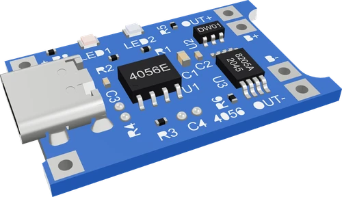
The TP4056 module is a linear charger for one Li-ion cell: it charges to a fixed 4.2 V (±1.5 %) at a current set by its PROG resistor, 1000 mA with 1.2 kΩ, and ends the charge when the current falls to a tenth of that (TP4056 datasheet, pp. 1, 3). Feed 5 V into its USB connector or IN+ and IN-, put one cell on B+ and B-, and take the load from OUT+ and OUT-, which run through a DW01A protector that cuts off near 4.3 V and 2.4 V (DW01x datasheet, p. 8). OUT+ is the raw cell voltage, so a 5 V board needs a boost converter and a 3.3 V board a regulator.
The TP4056 module is the small blue board makers use to charge a single lithium-ion or lithium-polymer cell, usually an 18650, from a USB port. At its heart is NanJing Top Power's TP4056, a complete constant-current/constant-voltage linear charger in an SOP-8 package that needs no external MOSFET, sense resistor or blocking diode (TP4056 datasheet, p. 1). The charge voltage is fixed at 4.2 V with 1.5 % accuracy, and the charge current is set by a single resistor on the PROG pin, up to 1000 mA (p. 1).
A charge runs in three phases. Below 2.9 V the chip trickle charges the cell at about 130 mA with the standard 1.2 kΩ resistor, then switches to full constant current, then holds 4.2 V while the current tapers, and it stops once the current has fallen to one tenth of the programmed value (pp. 1, 2). Thermal feedback lowers the current when the die gets hot, so a 1 A charge from a warm 5 V supply can run slower than the setting (p. 1). Two open-drain status pins drive the module's LEDs: one lights while charging, the other once the charge has terminated (pp. 2, 3).
The version with six pads and a protection IC is the one to use for powering projects. The cell goes on B+ and B-, and the load goes on OUT+ and OUT-, behind a DW01A protector and its dual MOSFET. The DW01A disconnects the cell when it rises past 4.30 V, when it falls below 2.40 V, or when the current through the MOSFETs produces more than 150 mV across them (DW01x datasheet, p. 8). What reaches OUT+ is the cell's own voltage, about 3.0 V to 4.2 V, not a regulated rail.
TP4056 USB-C Li-ion Charger pinout
| Pin | Function | Type |
|---|---|---|
| VIN | IN+ (5 V in)4.5–5 V | power in |
| GND_IN | IN- (ground) | power in |
| BAT_P | B+ (cell +) | passive |
| BAT_N | B- (cell -) | passive |
| VOUT | OUT+ (protected out) | power out |
| GND_OUT | OUT- (ground) | power in |
How to wire the TP4056 USB-C Li-ion Charger
| BAT_P | 18650 Li-ion Cell + Holder VCC | |
|---|---|---|
| BAT_N | 18650 Li-ion Cell + Holder GND | |
| VOUT | MT3608 Boost Converter Module VIN | |
| GND_OUT | MT3608 Boost Converter Module GND_IN |
Before you wire it
- The load on OUT+ / OUT−, never on B+: the protection only guards what is behind it.
- 5 V parts (an Arduino, 5 V sensors, servos): an MT3608 boost after OUT+ set to 5 V (mt3608-boost-module... vout=5), its output to the board's input pin: an ESP32 DevKit's VIN at vout=5, an Uno's or Nano's VIN at vout=9.
- A board that talks to parts powered from it shares its ground (OUT− / IN−).
- No battery on B+ / B− but one Li-ion cell; no reversed cell.
- No load on B+ (bypasses the protection).
- No OUT+ straight onto a 3.3 V part or a board's 3V3 pin (4.2 V full cell).
- Never put more than 8 V on IN+: the TP4056 takes 4.0 to 8.0 V
- Supply 5 V through the USB connector or the IN+ and IN- pads. The chip accepts 4.0 V to 8.0 V (TP4056 datasheet, p. 2), but it is a linear charger: everything above the cell's voltage is burned as heat, so a higher input mostly makes the board hotter and lets the thermal regulation cut the current (p. 1). 5 V is the right input.
- B+ and B- take exactly one Li-ion or Li-polymer cell, positive to B+. The chip charges to 4.2 V only (p. 1), so never connect two cells in series, alkaline AAs, NiMH cells or a LiFePO4 cell.
- Connect the load to OUT+ and OUT-, never to B+ and B-. Only OUT passes through the DW01A protector, which disconnects the cell below 2.40 V, above 4.30 V or on overcurrent (DW01x datasheet, p. 8). A load on the B pads can drain the cell past its safe discharge voltage.
- OUT+ follows the cell from about 3.0 V to 4.2 V. For a 5 V board, add a boost converter such as an MT3608 set to 5 V. For a 3.3 V board, use a low-dropout regulator: an AMS1117-3.3 needs about 1.1 V of headroom (AMS1117 datasheet, p. 3), more than a Li-ion cell gives. A Raspberry Pi Pico can take OUT+ straight on VSYS, which accepts 1.8 V to 5.5 V (Raspberry Pi Pico datasheet, p. 8).
- To charge a smaller cell, change the PROG resistor to the current the cell's datasheet allows: the TP4056 table runs from 10 kΩ for 130 mA to 1.2 kΩ for 1000 mA (TP4056 datasheet, p. 3).
- The TP4056's TEMP pin can suspend charging when a pack's thermistor reads too hot or too cold; grounding it disables the check (p. 2). With the pin grounded, nothing stops a charge in the cold, so keep the cell within its own charge temperature range, typically 0 °C to 45 °C for an 18650 such as LG's INR18650 MJ1 (LG MJ1 specification, p. 4).
- The DW01A protection trips on 150 mV across its MOSFETs, not at a fixed current.
- One LED lights while the cell charges and the other once it is full; the colours depend on the board.
Specifications
- Charge method
- Constant current / constant voltage, linearTP4056 datasheet, p. 1
- Charge voltage
- 4.2 V fixed, ±1.5 %TP4056 datasheet, p. 1
- Charge current
- Up to 1000 mA, set by RPROG (1.2 kΩ = 1000 mA, 2.4 kΩ = 500 mA)TP4056 datasheet, pp. 2, 3
- Input supply (VCC)
- 4.0 V to 8.0 V; absolute maximum 8 VTP4056 datasheet, pp. 1, 2
- Trickle charge
- Below 2.9 V, about 130 mA with RPROG = 1.2 kΩTP4056 datasheet, p. 2
- Charge termination
- When current falls to 1/10 of the programmed value (C/10)TP4056 datasheet, p. 1
- Battery drain when unpowered
- Under 2 µA on BAT in sleep modeTP4056 datasheet, p. 2
- Overcharge cutoff (DW01A)
- 4.30 V ±0.05 V, releases at 4.10 VFortune DW01x datasheet, Rev. 1.7, p. 8
- Over-discharge cutoff (DW01A)
- 2.40 V ±0.10 V, releases at 3.00 VFortune DW01x datasheet, Rev. 1.7, p. 8
- Overcurrent detection (DW01A)
- 150 mV across the MOSFET pair, 10 ms typical delayFortune DW01x datasheet, Rev. 1.7, p. 8
- Supply voltage
- 4.0–8.0 Vmaker's datasheet, checked 29 Oct 2026
- Dimensions
- 29.3 × 17.4 × 4.14 mm
- Weight
- 2 g
From the Generic (NanJing Top Power TP4056)'s datasheet, published by Generic (NanJing Top Power TP4056).
Common mistakes
Powering the project from B+ instead of OUT+
The B pads connect straight to the cell. Only OUT+ and OUT- pass through the DW01A, which disconnects the cell at 2.40 V and on overcurrent (DW01x datasheet, p. 8). Wired to B+, a project can drain the cell until it is damaged.
Feeding OUT+ into a 3.3 V pin or a 5 V pin
OUT+ is the cell's voltage, up to 4.2 V on a full cell (TP4056 datasheet, p. 1). That is too much for a 3V3 pin and too little for a 5 V rail or an ESP32 DevKit's VIN, whose AMS1117 needs about 1.1 V of headroom (AMS1117 datasheet, p. 3). Boost it to 5 V or regulate it to 3.3 V first.
Charging the wrong battery
The TP4056 charges to a fixed 4.2 V for a single Li-ion cell (TP4056 datasheet, p. 1). Two cells in series, alkaline or NiMH AAs, or a 3.2 V LiFePO4 cell are the wrong chemistry or voltage, and charging them can make them leak, swell or burn.
Expecting the charge to end with a load connected
The chip stops when the current into BAT falls to a tenth of the programmed value, 100 mA with the 1 A setting (TP4056 datasheet, p. 1). A project drawing about that much from OUT+ while it charges keeps the current above the threshold, so the done LED may never light and the cell is held at 4.2 V.
Using the 1 A setting on a small LiPo
Modules sold as 1 A chargers program 1000 mA, the TP4056 table's value for 1.2 kΩ (p. 3). A small pouch cell rated for less must have the PROG resistor raised, for example to 2.4 kΩ for 500 mA (p. 2).
TP4056 USB-C Li-ion Charger questions
How do I wire a TP4056 module to an 18650 and an Arduino or ESP32?
Put the cell on B+ and B-, plug USB into the module, and take power from OUT+ and OUT-. OUT+ is 3.0 V to 4.2 V, so feed it to an MT3608 boost set to 5 V and connect the boost's output to the board's VIN or 5V input, with all grounds common. The DW01A on the module then protects the cell against over-discharge at 2.40 V (DW01x datasheet, p. 8).
Can a TP4056 power a 3.3 V board directly?
No. OUT+ reaches 4.2 V on a full cell (TP4056 datasheet, p. 1), which is above what a 3.3 V chip accepts. Use a low-dropout 3.3 V regulator after OUT+, or a board with its own wide input, such as a Raspberry Pi Pico's VSYS, rated 1.8 V to 5.5 V (Raspberry Pi Pico datasheet, p. 8).
What do the TP4056 LEDs mean?
One LED lights while charging and the other once the charge has terminated (TP4056 datasheet, p. 3). On the common modules the first is red and the second blue or green. With no cell and a 10 µF capacitor on BAT, the done LED lights and the charge LED flickers with a 1 to 4 second period, and both stay dark when the input is too low (p. 3).
How do I change the TP4056 charging current?
Replace the PROG resistor. The datasheet gives 1.2 kΩ for 1000 mA, 2 kΩ for 580 mA, 3 kΩ for 400 mA, 5 kΩ for 250 mA and 10 kΩ for 130 mA (TP4056 datasheet, p. 3). Pick the current your cell's datasheet allows; LG's INR18650 MJ1, for example, takes up to 1.0 C, 3400 mA (LG MJ1 specification, p. 4).
Why is my TP4056 not charging or getting very hot?
If neither LED changes, check the input: the chip needs at least 4.0 V (TP4056 datasheet, p. 2) and a charge-only USB cable or a weak port can sag below it. A hot board is normal at 1 A: the TP4056 is linear, and its thermal feedback lowers the current to hold the die at about 145 °C (pp. 1, 2). A cell below 2.9 V charges slowly at first, at about 130 mA, until it recovers (p. 2).
TP4056 with or without protection: which do I need?
Take the six-pad version with a DW01A and its dual MOSFET when the cell powers a project. The plain four-pad board only charges; nothing stops the load from draining the cell, while the DW01A cuts off at 2.40 V, at 4.30 V and on overcurrent (DW01x datasheet, p. 8). A protected 18650 already carries its own protection and works with either.
Can I use the TP4056 to charge two 18650s in series?
No. It charges a single cell to 4.2 V (TP4056 datasheet, p. 1). Cells in parallel, matched and at the same voltage, form one larger cell it can charge; two in series need a 2S charger and a balancing protection board.
Build something with the TP4056 USB-C Li-ion Charger
Rechargeable ESP32 sensor node
An 18650, a TP4056 and an MT3608 at 5 V into the DevKit's VIN make a Wi-Fi sensor that charges from any USB port.
USB-rechargeable flashlight
Drive an LED from OUT+ through a constant-current driver and top it up from a phone charger.
Battery-powered Raspberry Pi Pico
Feed OUT+ straight into the Pico's VSYS, which accepts 1.8 V to 5.5 V, for a compact logger or game.
Solar garden light
A small 5 V solar panel on IN+ charges the cell by day, and the cell runs an LED at night.
Portable power bank
Pair the charger with a 5 V boost module to make a USB power bank from salvaged 18650 cells.
This page as plain Markdown, for ChatGPT, Claude or your own agent. /components/tp4056-charger-module.md