TMP36 Temperature Sensor
A low-voltage analog temperature sensor with a 0.5 V offset, so it reads below freezing on a single supply.
- Supply voltage2.7 V to 5.5 V (7 V absolute maximum)
- Transfer functionVOUT = 0.5 V + 10 mV/°C (750 mV at 25 °C)
- Specified range-40 °C to +125 °C, operation to 150 °C
- Accuracy, TMP36GT9Z (G grade)±1 °C typ, ±3 °C max at 25 °C; ±2 °C typ, ±4 °C max over range
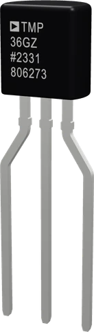
The TMP36 is an analog temperature sensor that runs from 2.7 V to 5.5 V and outputs 750 mV at 25 °C, rising 10 mV per °C, over -40 °C to +125 °C (ADI TMP35/36/37 datasheet Rev. F, p. 1). Wire +VS to 3.3 V or 5 V, GND to ground and VOUT to an analog input; temperature in °C is (volts - 0.5) × 100, because its output carries a 0.5 V offset (p. 8).
The TMP36 is a three-lead temperature sensor from Analog Devices. It outputs a voltage proportional to Celsius temperature at 10 mV/°C with a 0.5 V offset, so 0 °C reads 500 mV, 25 °C reads 750 mV and -40 °C reads 100 mV (ADI datasheet, pp. 1, 8). That offset is the reason it can measure below freezing without a negative supply.
It runs from a single 2.7 V to 5.5 V supply and draws under 50 µA, which keeps self-heating under 0.1 °C in still air (pp. 1, 3). That makes it equally at home on a 3.3 V ESP32 or Raspberry Pi Pico and on a 5 V Arduino. It is specified from -40 °C to +125 °C and keeps working to 150 °C with reduced accuracy (p. 1).
Accuracy depends on the grade. The datasheet gives ±1 °C typical at 25 °C and ±2 °C typical over temperature; the TO-92 TMP36GT9Z is the G grade, rated ±3 °C maximum at 25 °C and ±4 °C maximum over its range (pp. 3, 19). The output tolerates heavy capacitive loads, up to 10,000 pF without oscillating (pp. 3, 17), which helps on long wires.
TMP36 Temperature Sensor pinout
| Pin | Function | Type |
|---|---|---|
| VCC | 1 +VS (2.7-5.5 V)2.7 to 5.5 V | power in |
| VOUT | ADC 0.5 V + 10 mV/°C2 V | output |
| GND | 3 GND | power in |
How to wire the TMP36 Temperature Sensor
Pin by pin, for the board you have.
| TMP36 Temperature Sensor | Arduino Uno | Note |
|---|---|---|
| VCC | 5V | |
| VOUT | A0 | |
| GND | GND |
| TMP36 Temperature Sensor | ESP32 DevKit V1 | Note |
|---|---|---|
| VCC | 3V3 | |
| VOUT | GPIO33 (D33) | |
| GND | GND |
| TMP36 Temperature Sensor | Raspberry Pi Pico | Note |
|---|---|---|
| VCC | 3V3 | |
| VOUT | GP28 | |
| GND | GND |
TMP36 Temperature Sensor code
Every example here compiles for its board.
// TMP36 Temperature Sensor on Arduino Uno: wiring and a free simulation at https://www.tinkered.ai/components/tmp36
const int VOUT_PIN = A0;          // TMP36 VOUT
const float ADC_VREF = 5.0;       // the Uno's analog reference: its 5 V
const float ADC_STEPS = 1024.0;   // 10-bit ADC

void setup() {
  Serial.begin(9600);
}

void loop() {
  long sum = 0;
  for (int i = 0; i < 8; i++) sum += analogRead(VOUT_PIN);
  float volts = (sum / 8.0) * ADC_VREF / ADC_STEPS;
  float tempC = (volts - 0.5) * 100.0;      // 0.5 V at 0 °C, 10 mV per °C
  float tempF = tempC * 9.0 / 5.0 + 32.0;
  Serial.print("Temperature: ");
  Serial.print(tempC, 1);
  Serial.print(" C  ");
  Serial.print(tempF, 1);
  Serial.println(" F");
  delay(1000);
}
// TMP36 Temperature Sensor on ESP32 DevKit V1: wiring and a free simulation at https://www.tinkered.ai/components/tmp36
const int VOUT_PIN = 33;          // TMP36 VOUT on GPIO33 (ADC1)

void setup() {
  Serial.begin(9600);
  analogSetPinAttenuation(VOUT_PIN, ADC_11db);   // 11 dB, the widest range: Espressif rates it accurate to about 2.45 V
}

void loop() {
  // analogReadMilliVolts() applies the chip's own ADC calibration: the ESP32's
  // 12-bit analogRead() is not linear, so raw counts * 3.3 / 4095 reads off
  uint32_t mv = 0;
  for (int i = 0; i < 8; i++) mv += analogReadMilliVolts(VOUT_PIN);
  float volts = mv / 8.0 / 1000.0;
  float tempC = (volts - 0.5) * 100.0;      // 0.5 V at 0 °C, 10 mV per °C
  float tempF = tempC * 9.0 / 5.0 + 32.0;
  Serial.print("Temperature: ");
  Serial.print(tempC, 1);
  Serial.print(" C  ");
  Serial.print(tempF, 1);
  Serial.println(" F");
  delay(1000);
}
// TMP36 Temperature Sensor on Raspberry Pi Pico: wiring and a free simulation at https://www.tinkered.ai/components/tmp36
const int VOUT_PIN = 28;          // TMP36 VOUT on GP28 (ADC2)
const float ADC_VREF = 3.3;       // the Pico's ADC reference: its 3.3 V rail
const float ADC_STEPS = 4096.0;   // 12 bits, set in setup() (arduino-pico defaults to 10)

void setup() {
  Serial.begin(9600);
  analogReadResolution(12);
}

void loop() {
  long sum = 0;
  for (int i = 0; i < 8; i++) sum += analogRead(VOUT_PIN);
  float volts = (sum / 8.0) * ADC_VREF / ADC_STEPS;
  float tempC = (volts - 0.5) * 100.0;      // 0.5 V at 0 °C, 10 mV per °C
  float tempF = tempC * 9.0 / 5.0 + 32.0;
  Serial.print("Temperature: ");
  Serial.print(tempC, 1);
  Serial.print(" C  ");
  Serial.print(tempF, 1);
  Serial.println(" F");
  delay(1000);
}
Before you wire it
- VCC to the board's 3.3 V or 5 V pin, GND to GND, VOUT to an ANALOG input: A0-A5 on an Uno, Nano or UNO R4, A0-A15 on a Mega, GP26-GP28 on a Pico, A0 on an ESP8266 NodeMCU, an ADC1 pin on an ESP32 (GPIO32-39; GPIO0-4 on a C3, GPIO1-10 on an S3).
- Convert with the board's own analog reference and resolution (table below): volts = raw * VREF / STEPS, then °C = (volts - 0.5) * 100.
- Average a few readings (8 to 16) when the reading jitters: one ADC step is 4.9 mV on a 5 V Uno, about half a degree.
- No swapping +VS and GND: turned round, a TMP36 gets too hot to touch within seconds and is destroyed. Check the flat face before wiring.
- No pull-up or pull-down resistor on VOUT, and no LED on it: the output drives 50 µA at most.
- No digital pin for VOUT: digitalRead cannot read a voltage.
- No more than 5.5 V on +VS (a 9 V battery straight on it destroys it at 7 V).
- (ESP32) NO ADC2 pin (GPIO 0/2/4/12-15/25-27) when the sketch uses Wi-Fi: ADC2 reads nothing while the radio runs.
- Power +VS from the board's 3.3 V or 5 V pin; anything from 2.7 V to 5.5 V works (ADI datasheet, p. 3). Its output stays under 2.0 V across its range (p. 3), safe for any ADC.
- Read VOUT on an analog pin and convert with °C = (volts - 0.5) × 100, using the ADC's real reference: 5.0 V on a default Uno, 3.3 V on an ESP32, ESP8266 or Pico.
- Place a 0.1 µF ceramic capacitor from +VS to GND, close to the sensor; ADI adds a 2.2 µF tantalum in parallel for strong RF noise (p. 10).
- For long cables add a 750 Ω resistor in series with VOUT; with the cable's capacitance it forms a low-pass filter (p. 17).
- Keep loads light: the output supplies 50 µA at most (p. 3), so never put an LED, a pull-up or a pull-down on VOUT.
- Accuracy is ±3 °C at most at 25 °C (TO-92).
Specifications
- Supply voltage
- 2.7 V to 5.5 V (7 V absolute maximum)ADI TMP35/36/37 datasheet Rev. F, pp. 3, 4
- Transfer function
- VOUT = 0.5 V + 10 mV/°C (750 mV at 25 °C)ADI TMP35/36/37 datasheet Rev. F, pp. 3, 8
- Specified range
- -40 °C to +125 °C, operation to 150 °CADI TMP35/36/37 datasheet Rev. F, p. 1
- Accuracy, TMP36GT9Z (G grade)
- ±1 °C typ, ±3 °C max at 25 °C; ±2 °C typ, ±4 °C max over rangeADI TMP35/36/37 datasheet Rev. F, pp. 3, 19
- Supply current
- 50 µA max, unloadedADI TMP35/36/37 datasheet Rev. F, p. 3
- Output load current
- 50 µA max; 250 µA short-circuit limitADI TMP35/36/37 datasheet Rev. F, p. 3
- Capacitive load
- 1,000 pF min, 10,000 pF typical without oscillationADI TMP35/36/37 datasheet Rev. F, p. 3
- Turn-on time
- 0.5 ms typ, 1 ms maxADI TMP35/36/37 datasheet Rev. F, p. 3
- Linearity
- 0.5 °C typicalADI TMP35/36/37 datasheet Rev. F, p. 3
- TO-92 pinout
- 1 +VS, 2 VOUT, 3 GND (bottom view)ADI TMP35/36/37 datasheet Rev. F, pp. 1, 10
- Interface
- Analog
- Dimensions
- 5.55 × 3.68 × 18.33 mm
- Weight
- 0.2 g
From the Analog Devices's datasheet, published by Analog Devices.
Common mistakes
Wiring it backwards
Seen from the bottom, the TO-92 pins are 1 +VS, 2 VOUT, 3 GND (ADI datasheet, p. 1). Reversed, the sensor gets very hot within seconds and is destroyed. Check the flat face before powering up.
Forgetting the 0.5 V offset
The TMP36 reads 500 mV at 0 °C (p. 8). Multiplying the voltage by 100 without subtracting 0.5 V first reads 50 °C too high.
Keeping the Uno's 5.0 V in a 3.3 V board's code
On an ESP32, ESP8266 or Pico the ADC reference is 3.3 V. Converting with 5.0 makes a 25 °C room read around 64 °C.
Exceeding 5.5 V on +VS
The supply range ends at 5.5 V and the absolute maximum is 7 V (pp. 3, 4). A 9 V battery straight on the sensor destroys it.
Expecting better than the grade allows
The TO-92 TMP36GT9Z is rated ±3 °C max at 25 °C and ±4 °C max over temperature (pp. 3, 19). Calibrate against a known thermometer if you need tighter readings.
TMP36 Temperature Sensor questions
Does the TMP36 work at 3.3 V?
Yes. It is specified from 2.7 V to 5.5 V (ADI datasheet, p. 3), so the 3.3 V pin of an ESP32, ESP8266 or Raspberry Pi Pico powers it directly. Convert with the 3.3 V reference: volts = raw × 3.3 / 4095 on a 12-bit ESP32.
What is the TMP36 formula?
°C = (VOUT - 0.5 V) × 100. The output is 0.5 V at 0 °C and rises 10 mV/°C, giving 750 mV at 25 °C (ADI datasheet, pp. 3, 8). For Fahrenheit, multiply °C by 9/5 and add 32.
Why does my TMP36 read about -50 °C or jump around?
-50 °C means VOUT reads 0 V: the sensor is unpowered, turned round (pins 1 +VS, 2 VOUT, 3 GND from the bottom, p. 1) or VOUT is on the wrong pin. Jumpy readings call for the 0.1 µF bypass capacitor ADI shows (p. 10), averaging, and a 750 Ω series resistor on long wires (p. 17).
TMP36 vs LM35: which is better?
Both scale at 10 mV/°C. The TMP36 runs from 2.7 V and reads down to -40 °C on a single supply thanks to its 0.5 V offset (ADI datasheet, pp. 1, 8). The LM35 needs 4 V to 30 V, has no offset, and the LM35D is ±1.5 °C max at 25 °C against the TMP36GT9Z's ±3 °C (TI LM35 datasheet, pp. 4, 9; ADI pp. 3, 19). Pick the TMP36 for 3.3 V boards and freezing temperatures, the LM35 for tighter accuracy on 5 V.
How accurate is the TMP36?
Typically ±1 °C at 25 °C and ±2 °C over -40 °C to +125 °C (ADI datasheet, p. 1). The guaranteed limits for the TO-92 TMP36GT9Z, the G grade, are ±3 °C at 25 °C and ±4 °C over temperature (pp. 3, 19).
Can I put the TMP36 on a long cable?
Yes. It drives capacitive loads up to 10,000 pF without oscillating, and ADI recommends a 750 Ω resistor in series with the output to speed up settling and filter noise (ADI datasheet, p. 17).
Build something with the TMP36 Temperature Sensor
- Build this
Indoor and outdoor thermometer
Read temperatures below freezing on a single supply and show them on a display.
- Build this
Battery-powered weather logger
Its sub-50 µA draw suits an ESP32 or Pico that sleeps between readings.
- Build this
Thermostat
Switch a heater or fan relay around a set point with a little hysteresis.
- Build this
Freezer alarm
Beep or send a Wi-Fi notification when a freezer warms past a threshold.
This page as plain Markdown, for ChatGPT, Claude or your own agent. /components/tmp36.md