NTC Thermistor (10kΩ)
A 10 kΩ NTC thermistor, B = 3950 K, whose resistance falls as it warms: the cheapest way to read temperature on an analog pin.
- Resistance at 25 °C10 kΩ ±1 %
- B constant (25/50 °C)3950 K ±1 %
- Resistance at 0 / 50 / 100 °C32.755 kΩ / 3.588 kΩ / 0.668 kΩ (typical)
- Operating range-30 °C to +105 °C
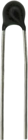
A 10 kΩ NTC thermistor is a resistor that measures 10 kΩ ±1 % at 25 °C and drops as it heats, following a B constant of 3950 K (Hongjiacheng HNTC-103F3950FB datasheet, p. 1). Wire it as a voltage divider with a 10 kΩ fixed resistor, thermistor from VCC to the junction and resistor from the junction to GND, and read the junction on an analog pin; the junction sits at half the supply at 25 °C. Convert the resistance to temperature with the B-parameter equation or the maker's R-T table (pp. 2, 4, 5).
An NTC (negative temperature coefficient) thermistor is a two-lead ceramic resistor whose resistance falls as its temperature rises. This MF52-style bead is rated 10 kΩ ±1 % at 25 °C with a B25/50 constant of 3950 K ±1 % and works from -30 °C to +105 °C (Hongjiacheng datasheet, p. 1). It is not polarised, so either lead can go either way.
A microcontroller cannot measure resistance directly, so the thermistor goes into a voltage divider with a fixed resistor. With a 10 kΩ resistor, the divider's midpoint sits at exactly half the supply at 25 °C and moves strongly near room temperature: the maker's table gives 32.755 kΩ at 0 °C, 3.588 kΩ at 50 °C and 0.668 kΩ at 100 °C (pp. 4, 5).
Firmware turns the ADC reading back into a resistance, then into a temperature. The B-parameter equation, 1/T = 1/T25 + ln(R/R25)/B with T in kelvin, uses the same 25 °C and 50 °C points the maker uses to define B (p. 2), so it is exact there and drifts slowly away from them. For the best accuracy across the range, interpolate the R-T table instead.
How to wire the NTC Thermistor (10kΩ)
Pin by pin, for the board you have.
| NTC Thermistor (10kΩ) | Arduino Uno | Note |
|---|---|---|
| pin1 | 5V | |
| pin2 | A0 | |
| pin2 | GND | through a 10 kΩ resistor |
| NTC Thermistor (10kΩ) | ESP32 DevKit V1 | Note |
|---|---|---|
| pin1 | 3V3 | |
| pin2 | GPIO33 (D33) | |
| pin2 | GND | through a 10 kΩ resistor |
| NTC Thermistor (10kΩ) | Raspberry Pi Pico | Note |
|---|---|---|
| pin1 | 3V3 | |
| pin2 | GP28 | |
| pin2 | GND | through a 10 kΩ resistor |
Before you wire it
- The NTC is a passive 2-terminal resistor: it must be wired as a voltage divider with a fixed 10kOhm resistor.
- One NTC lead connects to VCC; the other NTC lead connects to the divider junction.
- The fixed resistor connects from that same junction to GND.
- The junction must connect to an analog input pin: A0-A5 on Uno/Nano; on ESP32 prefer ADC1 (GPIO 32-39), which keeps working with WiFi on.
- Heat lowers the NTC resistance, raising the junction voltage, so analogRead goes UP as it gets hotter. Keep the firmware maths consistent with that.
- No connecting an NTC lead directly to an analog pin WITHOUT the fixed resistor: with no divider the ADC node floats and reads garbage.
- No connecting the junction to a digital-only pin.
- (ESP32) no using an ADC2 GPIO (0/2/4/12-15/25-27) when WiFi is on: ADC2 is unavailable while the radio runs.
- No putting the resistor on top and the NTC to GND.
- Wire a divider: VCC to one thermistor lead, the other lead to the junction, a 10 kΩ resistor from the junction to GND, and the junction to an analog input. With the thermistor on top, the reading rises as it warms.
- Convert in code: R_ntc = R_fixed × (ADC_max / raw - 1), then T(K) = 1 / (1/298.15 + ln(R_ntc / 10000) / 3950), and subtract 273.15 for °C.
- Mind self-heating. The bead heats 1 °C for every 2.0 mW it dissipates and is rated 10 mW at most (Hongjiacheng datasheet, p. 1). A 5 V, 10 kΩ divider puts about 0.6 mW into it at 25 °C, around 0.3 °C of self-heating; power the divider from 3.3 V or switch it from a GPIO when that matters.
- On an ESP32 use an ADC1 pin (GPIO 32 to 39); ADC2 stops working while Wi-Fi runs.
- When soldering, keep the joint at least 2 mm from the coating, below 360 °C, for under 3 s (p. 3).
Specifications
- Resistance at 25 °C
- 10 kΩ ±1 %Hongjiacheng HNTC-103F3950FB-100P datasheet Rev. 1.1, p. 1
- B constant (25/50 °C)
- 3950 K ±1 %Hongjiacheng HNTC-103F3950FB-100P datasheet Rev. 1.1, p. 1
- Resistance at 0 / 50 / 100 °C
- 32.755 kΩ / 3.588 kΩ / 0.668 kΩ (typical)Hongjiacheng HNTC-103F3950FB-100P datasheet Rev. 1.1, pp. 4, 5
- Operating range
- -30 °C to +105 °CHongjiacheng HNTC-103F3950FB-100P datasheet Rev. 1.1, p. 1
- Dissipation constant
- 2.0 mW/°C min, still airHongjiacheng HNTC-103F3950FB-100P datasheet Rev. 1.1, p. 1
- Maximum power
- 10 mW at 25 °CHongjiacheng HNTC-103F3950FB-100P datasheet Rev. 1.1, p. 1
- Response time
- 15 s max in liquid (25 °C to 50 °C, 63.2 %)Hongjiacheng HNTC-103F3950FB-100P datasheet Rev. 1.1, p. 1
- Body
- 2.8 mm max diameter, 7.5 mm max head, 100 mm leadsHongjiacheng HNTC-103F3950FB-100P datasheet Rev. 1.1, p. 3
From the Zhuhai Hongjiacheng (HNTC-103F3950FB)'s datasheet, published by Zhuhai Hongjiacheng (HNTC-103F3950FB).
Common mistakes
No fixed resistor
A thermistor alone on an analog pin gives the ADC no reference, so the pin floats. It must be one half of a divider with a fixed resistor, 10 kΩ to match the thermistor's 25 °C value.
Formula written for the other divider orientation
With the thermistor on top the junction voltage rises with heat; with it at the bottom the voltage falls. Use the resistance formula that matches your wiring, or every reading runs backwards.
Using the wrong B value
10 kΩ NTCs are made with different B values; the maker's own part-number example is a 3380 K part, while this one is 3950 K (Hongjiacheng datasheet, p. 1). Plugging in the wrong B shifts every reading away from 25 °C.
Reading it past its range
This bead is rated -30 °C to +105 °C (p. 1). Above that it is outside the maker's table and the B-equation's error grows.
Heating it with the measuring current
Every 2.0 mW in the bead warms it about 1 °C (p. 1). A low-value fixed resistor or a high supply raises the current and the error; keep the divider at 10 kΩ.
NTC Thermistor (10kΩ) questions
Can I use a 10k NTC thermistor with a 3.3 V board?
Yes. A thermistor is a passive resistor, so the divider works from any supply; power it from the board's 3.3 V pin so the junction never exceeds the ADC's range. At 25 °C the junction sits at 1.65 V with a 10 kΩ resistor, and the lower supply also cuts self-heating, which is 1 °C per 2.0 mW (Hongjiacheng datasheet, p. 1).
How do I convert thermistor resistance to temperature?
Use the B-parameter equation: 1/T = 1/298.15 + ln(R/10000)/3950, with T in kelvin. The maker defines B from the resistances at 25 °C and 50 °C (Hongjiacheng datasheet, p. 2), so the equation is exact there; for wider ranges, interpolate the maker's R-T table (pp. 4, 5).
Why does my thermistor read wrong, or backwards?
Readings that fall as it warms mean the code assumes the other divider orientation. Readings stuck at 0 or the maximum mean an open or shorted divider. Readings off by a few degrees usually mean the wrong B value; this part is 3950 K (Hongjiacheng datasheet, p. 1).
What fixed resistor should I use with a 10k thermistor?
10 kΩ, the thermistor's resistance at 25 °C (Hongjiacheng datasheet, p. 1). That centres the divider at half the supply at room temperature, where the reading changes fastest per degree.
What temperature range can a 10k B3950 thermistor read?
This MF52 bead is rated -30 °C to +105 °C (Hongjiacheng datasheet, p. 1). Its resistance spans 179.267 kΩ at -30 °C down to 0.577 kΩ at 105 °C (pp. 4, 5).
Thermistor vs DS18B20 or TMP36: which should I use?
A thermistor costs the least and responds fast, but needs a divider and a conversion in code, and its accuracy depends on your resistor and ADC. Digital sensors like the DS18B20 report calibrated temperatures directly; analog chips like the TMP36 give a linear voltage. Choose the thermistor for cheap, compact sensing or for probes in tight spots.
Build something with the NTC Thermistor (10kΩ)
- Build this
3D printer hotend and bed sensing
NTC thermistors read nozzle and bed temperature on most hobby 3D printers.
- Build this
Battery pack temperature monitor
Tape a bead to the cells and stop charging when they run warm.
- Build this
Aquarium or brewing thermometer
Seal the bead in a probe and read liquid temperature on an Arduino.
- Build this
Fan or heater thermostat
Switch a relay or MOSFET around a set point read from the divider.
This page as plain Markdown, for ChatGPT, Claude or your own agent. /components/thermistor-ntc-10k.md