TM1637 4-Digit Display with a Raspberry Pi Pico
A red 4-digit 7-segment display with a center colon, driven by the Titan Micro TM1637 chip over just two signal wires.
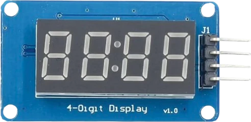
The TM1637 display needs only two Raspberry Pi Pico GPIOs, CLK on GP0 and DIO on GP1, which the library bit-bangs, plus 5 V from VBUS, with both lines through a bidirectional level shifter. It is not I2C, so it never shares GP4 and GP5 with the Pico's I2C parts or shows on an I2C scan.
Wiring the TM1637 4-Digit Display to the Raspberry Pi Pico
Pin by pin.
| TM1637 4-Digit Display | Raspberry Pi Pico | Note |
|---|---|---|
| CLK | GP0 | through a level shifter (a BSS138 board): the module pulls CLK up to its 5 V |
| DIO | GP1 | through a level shifter (a BSS138 board): the module pulls DIO up to its 5 V |
| VCC | VBUS | |
| GND | GND |
- VCC is on VBUS, which gives about 5 V only while the board is powered from USB.
- The TM1637 is rated for a 4.5 to 5.5 V supply and reads a high from 0.7 × VDD (3.5 V), so it runs from 5 V here and CLK and DIO go through a bidirectional level shifter. Powered from 3.3 V many modules light, but outside the datasheet's range.
What to know on the Raspberry Pi Pico
- The TM1637 is specified for 5 V ± 10 % and reads a high at 0.7 x VDD, 3.5 V. The page therefore powers it from VBUS and level-shifts CLK and DIO; on the Pico's 3V3 the display usually lights, but outside that range.TM1637 datasheet V2.1, pp. 2, 14
- The module's pull-ups on CLK and DIO go to its VCC, so at 5 V they would hold GP0 and GP1 above the RP2040's IOVDD + 0.5 V rating; the shifter keeps the Pico's side at 3.3 V.Titan Micro TM1637 datasheet V2.1, application circuit; RP2040 datasheet, section 5.5.3.1
- Any two GPIOs work; the protocol has no address, so a second display needs its own pair of pins.Titan Micro TM1637 datasheet V2.1, p. 2
TM1637 4-Digit Display code for the Raspberry Pi Pico
Compiled for rp2040:rp2040:rpipico on 2026-10-30.
// TM1637 4-Digit Display on Raspberry Pi Pico: wiring and a free simulation at https://www.tinkered.ai/components/tm1637-4digit-display/raspberry-pi-pico
#include <TM1637.h>

#define CLK 0
#define DIO 1

TM1637 tm(CLK, DIO);

void setup() {
  tm.init();
  tm.set(BRIGHT_TYPICAL);          // 0-7; nothing lights until this is sent
}

void loop() {
  static int n = 0;
  tm.display(0, (n / 1000) % 10);
  tm.display(1, (n / 100) % 10);
  tm.display(2, (n / 10) % 10);
  tm.display(3, n % 10);
  tm.point(n % 2 ? POINT_ON : POINT_OFF);   // colon blinks once a second
  n = (n + 1) % 10000;
  delay(1000);
}
TM1637 4-Digit Display on the Raspberry Pi Pico: questions
Can I run a TM1637 display from the Pico's 3.3 V?
It usually lights, but its datasheet specifies 5 V ± 10 % (TM1637 datasheet V2.1, p. 2). The page's wiring is the in-spec build: VBUS for power, and CLK and DIO shifted to 5 V.
Why is my TM1637 blank on the Pico?
The display stays dark until set() sends the display-on command; the sketch calls tm.set(BRIGHT_TYPICAL) after init(). Check CLK on GP0 and DIO on GP1.
Can the TM1637 share the Pico's I2C pins?
No. Its protocol carries no address, so another device on the same lines corrupts every frame. Give it its own two GPIOs.
Keep going
This guide as plain Markdown. /components/tm1637-4digit-display/raspberry-pi-pico.md