TCRT5000 IR Line Sensor
A reflective infrared line sensor that tells white from black a few millimetres above a surface.
- Peak operating distance2.5 mm
- Operating range0.2 mm to 15 mm (relative collector current above 20 %)
- Emitter wavelength950 nm infrared
- DetectorPhototransistor with daylight-blocking filter
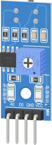
The TCRT5000 module is a reflective line sensor: Vishay's TCRT5000 pairs a 950 nm infrared emitter with a phototransistor behind a daylight filter, strongest 2.5 mm from the surface and usable from 0.2 to 15 mm (Vishay TCRT5000 datasheet, p. 1). Wire VCC to 3.3 V or 5 V, GND to GND, A0 to an analog pin and D0 to a digital pin; A0 falls over white, and D0 from the LM393 comparator goes LOW over white and stays HIGH over a black line.
The TCRT5000 module is the small blue line-tracking board used under most line-follower robots. Vishay's TCRT5000 sits at one end: an infrared emitter and a phototransistor side by side in a leaded package that blocks visible light, with a daylight-blocking filter on the detector (Vishay TCRT5000 datasheet, p. 1). The board adds an LM393 comparator, a threshold potentiometer, a power LED and a switch LED.
The emitter shines continuously. A light surface such as white paper reflects the infrared back to the phototransistor, which pulls the analog output A0 down; a black line or empty space reflects little, so A0 stays near VCC. The LM393 compares A0 with the potentiometer's setting and drives D0: LOW, with the switch LED lit, over a reflective surface, and HIGH over black or with nothing in reach.
Height matters more than anything else. The sensor gives its maximum signal 2.5 mm from the surface and keeps more than 20 % of it from 0.2 mm to 15 mm (Vishay TCRT5000 datasheet, p. 1; Fig. 9, p. 4). Mount it a few millimetres above the track; much higher and white and black start to read the same. It is a surface reflection sensor, not a distance or obstacle sensor.
TCRT5000 IR Line Sensor pinout
| Pin | Function | Type |
|---|---|---|
| AO | ADC the phototransistor's node: lower the more IR is reflected | output |
| DO | Digital | output |
| GND | GND | power in |
| VCC | VCC (3.3-5 V)3.3–5 V | power in |
How to wire the TCRT5000 IR Line Sensor
Pin by pin, for the board you have.
| TCRT5000 IR Line Sensor | Arduino Uno | Note |
|---|---|---|
| VCC | 5V | |
| GND | GND | |
| AO | A0 | |
| DO | D2 |
| TCRT5000 IR Line Sensor | ESP32 DevKit V1 | Note |
|---|---|---|
| VCC | 3V3 | |
| GND | GND | |
| AO | GPIO33 (D33) | |
| DO | GPIO13 (D13) |
| TCRT5000 IR Line Sensor | Raspberry Pi Pico | Note |
|---|---|---|
| VCC | 3V3 | |
| GND | GND | |
| AO | GP28 | |
| DO | GP0 |
TCRT5000 IR Line Sensor code
Every example here compiles for its board.
// TCRT5000 IR Line Sensor on Arduino Uno: wiring and a free simulation at https://www.tinkered.ai/components/tcrt5000-module
const int AO_PIN = A0;   // TCRT5000 A0: low over white, high over black
const int DO_PIN = 2;    // TCRT5000 D0: LOW over white, HIGH over black

// halfway between white (about 50) and black (about 930), with a margin either side
const int TO_BLACK = 600;  // above this: black
const int TO_WHITE = 400;  // below this: white
bool onLine = false;

void setup() {
  Serial.begin(9600);
  pinMode(DO_PIN, INPUT);  // the module has its own pull-up
  Serial.println("TCRT5000 ready");
}

void loop() {
  int level = analogRead(AO_PIN);
  if (!onLine && level > TO_BLACK) onLine = true;
  else if (onLine && level < TO_WHITE) onLine = false;

  Serial.print("A0 ");
  Serial.print(level);
  Serial.print("  D0 ");
  Serial.print(digitalRead(DO_PIN) == HIGH ? "HIGH" : "LOW");
  Serial.println(onLine ? "  line" : "  white");
  delay(100);
}
// TCRT5000 IR Line Sensor on ESP32 DevKit V1: wiring and a free simulation at https://www.tinkered.ai/components/tcrt5000-module
const int AO_PIN = 33;   // TCRT5000 A0: low over white, high over black
const int DO_PIN = 13;    // TCRT5000 D0: LOW over white, HIGH over black

// the ESP32 reads 12 bits: halfway between white (about 200) and black (about 3700), with a margin either side
const int TO_BLACK = 2400;  // above this: black
const int TO_WHITE = 1600;  // below this: white
bool onLine = false;

void setup() {
  Serial.begin(9600);
  pinMode(DO_PIN, INPUT);  // the module has its own pull-up
  Serial.println("TCRT5000 ready");
}

void loop() {
  int level = analogRead(AO_PIN);
  if (!onLine && level > TO_BLACK) onLine = true;
  else if (onLine && level < TO_WHITE) onLine = false;

  Serial.print("A0 ");
  Serial.print(level);
  Serial.print("  D0 ");
  Serial.print(digitalRead(DO_PIN) == HIGH ? "HIGH" : "LOW");
  Serial.println(onLine ? "  line" : "  white");
  delay(100);
}
// TCRT5000 IR Line Sensor on Raspberry Pi Pico: wiring and a free simulation at https://www.tinkered.ai/components/tcrt5000-module
const int AO_PIN = 28;   // TCRT5000 A0: low over white, high over black
const int DO_PIN = 0;    // TCRT5000 D0: LOW over white, HIGH over black

// halfway between white (about 50) and black (about 930), with a margin either side
const int TO_BLACK = 600;  // above this: black
const int TO_WHITE = 400;  // below this: white
bool onLine = false;

void setup() {
  Serial.begin(9600);
  pinMode(DO_PIN, INPUT);  // the module has its own pull-up
  Serial.println("TCRT5000 ready");
}

void loop() {
  int level = analogRead(AO_PIN);
  if (!onLine && level > TO_BLACK) onLine = true;
  else if (onLine && level < TO_WHITE) onLine = false;

  Serial.print("A0 ");
  Serial.print(level);
  Serial.print("  D0 ");
  Serial.print(digitalRead(DO_PIN) == HIGH ? "HIGH" : "LOW");
  Serial.println(onLine ? "  line" : "  white");
  delay(100);
}
Before you wire it
- A0-A5 on an Uno or Nano, A0-A15 on a Mega.
- An ADC1 pin on an ESP32 (GPIO32-39) or ESP32-S3 (GPIO1-10): ADC2 reads nothing while Wi-Fi runs.
- GPIO0-4 on an ESP32-C3, GP26-GP28 on a Pico, A0 on an ESP8266 NodeMCU or D1 mini.
- The ESP-01S has no analog input: use D0 only.
- DO to any digital input with pinMode(pin, INPUT): the module has its own pull-up. D0 LOW means white (reflecting), HIGH means black (the line) or nothing.
- A0 is the raw reading: on an ESP32, ESP32-S3 and ESP32-C3 analogRead() returns 0-4095 (12 bits); on a Pico (arduino-pico) and elsewhere it returns 0-1023 unless analogReadResolution() changes it. Decide white or black against a threshold taken from the readings over each (halfway between them), with a margin either side so the decision does not chatter at the edge.
- Mount it 3-8 mm above the surface (2.5 mm is its strongest). Never touching: flat on the surface it reads black.
- To count stripes or turns (an encoder disc, a tachometer), count D0's edges: attachInterrupt(digitalPinToInterrupt(pin), isr, RISING) (white to black), the ISR only incrementing a volatile counter. On an ESP8266 or ESP32 the ISR must be void IRAM_ATTR isr(); for a sketch that also builds for an Arduino, add #ifndef IRAM_ATTR / #define IRAM_ATTR / #endif at the top.
- No "D0 HIGH means white": D0 is LOW over white, HIGH over black.
- No "A0 rises over white": A0 falls the more the surface reflects.
- No 5 V on VCC with a 3.3 V board (ESP32, ESP8266, Pico, STM32).
- No extra pull-up or pull-down on D0 or A0: the module has its own 10 kΩ on each.
- Do not promise a distance reading or detection beyond about 15 mm: it is a reflection sensor for a surface a few millimetres away. For an obstacle a few centimetres off use an FC-51; for a distance, a VL53L0X or an HC-SR04.
- Power VCC from the same voltage as your board's logic: 5 V on an Uno or Nano, 3.3 V on an ESP32, ESP8266 or Raspberry Pi Pico. A0 and D0 swing up to VCC, so a module on 5 V would overdrive a 3.3 V input.
- Take power from the 5 V or 3V3 pin, never from a GPIO: the emitter shines continuously and is rated for up to 60 mA (Vishay TCRT5000 datasheet, p. 1).
- A0 goes to an analog input; D0 to any digital input with pinMode(pin, INPUT). The board has its own pull-ups, so add none. D0 LOW means white, HIGH means black or nothing in reach.
- Mount the sensor a few millimetres above the surface, close to its 2.5 mm peak (Vishay TCRT5000 datasheet, p. 1). Pressed flat against the surface, the emitter's light cannot reach the detector and everything reads as black.
- Pick the white/black threshold from real readings over each surface, halfway between them, with a small margin either side so the decision does not flicker at the line's edge.
- Vishay gives a usable range of 0.2 to 15 mm.
Specifications
- Peak operating distance
- 2.5 mmVishay TCRT5000 datasheet, p. 1
- Operating range
- 0.2 mm to 15 mm (relative collector current above 20 %)Vishay TCRT5000 datasheet, p. 1
- Emitter wavelength
- 950 nm infraredVishay TCRT5000 datasheet, p. 1
- Detector
- Phototransistor with daylight-blocking filterVishay TCRT5000 datasheet, p. 1
- Emitter forward current
- 60 mA maximum; VF 1.25 V typical at 60 mAVishay TCRT5000 datasheet, pp. 1, 2
- Collector current
- 1 mA typical (0.5 to 2.1 mA) at IF = 10 mA, VCE = 5 V, 12 mm from a mirrorVishay TCRT5000 datasheet, p. 2
- Ambient temperature
- -25 °C to +85 °CVishay TCRT5000 datasheet, p. 2
- Sensor package
- 10.2 × 5.8 × 7 mmVishay TCRT5000 datasheet, p. 1
- Comparator
- LM393, open-collector output; inputs 0 V to VCC minus 1.5 VTI LM393 datasheet (SLCS005AH), pp. 8, 17
- Module pins
- A0 (analog), D0 (digital), GND, VCCModule board (no maker datasheet)
- Supply voltage
- 3.3–5 V
- Maximum supply voltage
- 5.5 V
- Interface
- Analog
- Dimensions
- 14 × 14.3 × 38 mm
- Weight
- 2.5 g
From the Vishay TCRT5000 (generic MH-Sensor-Series module)'s datasheet, published by Vishay TCRT5000 (generic MH-Sensor-Series module).
Common mistakes
Mounting it too high
Past about 15 mm the reflected signal drops below a fifth of its peak (Vishay TCRT5000 datasheet, p. 1; Fig. 9, p. 4), and white and black read almost the same. Bring the sensor down to a few millimetres.
Reading D0 HIGH as white
D0 goes LOW over a reflective (white) surface and HIGH over a black line or empty space. Line-follower code written the other way round steers away from the line.
Expecting A0 to rise over white
More reflected light turns the phototransistor on harder and pulls A0 down, so white reads low and black reads high.
Testing it in direct sunlight
The daylight filter (Vishay TCRT5000 datasheet, p. 1) handles room lighting, but direct sun on the surface contains plenty of infrared and pulls A0 down on its own. Shade the sensor or test indoors.
Using it as an obstacle sensor
Its operating range ends at 15 mm (Vishay TCRT5000 datasheet, p. 1). For objects several centimetres away use an FC-51 IR obstacle sensor; for a distance, an HC-SR04 or VL53L0X.
TCRT5000 IR Line Sensor questions
Can I use the TCRT5000 module with an ESP32 or Raspberry Pi Pico?
Yes. Power it from 3.3 V so A0 and D0 never exceed the 3.3 V input limit, put A0 on an ADC pin and D0 on any GPIO.
What height should the TCRT5000 be above the line?
As close as practical to 2.5 mm, where Vishay rates its peak signal; it stays usable from 0.2 mm to 15 mm (Vishay TCRT5000 datasheet, p. 1). Most line followers mount it a few millimetres above the floor.
Is D0 HIGH or LOW over a black line?
HIGH. Black reflects little infrared, so the comparator output stays released and the pull-up holds D0 HIGH; over white it goes LOW and the switch LED lights.
Why do black and white read the same on my TCRT5000?
Usually the sensor is too far from the surface or pressed flat on it. Its signal peaks at 2.5 mm and falls off quickly past that (Vishay TCRT5000 datasheet, p. 1; Fig. 9, p. 4), so set it a few millimetres up, then re-tune the potentiometer.
What wavelength does the TCRT5000 use?
Its emitter is infrared: Vishay lists 950 nm in the features (p. 1) and a 940 nm peak wavelength in the characteristics table (p. 2). The detector's daylight-blocking filter keeps most visible light out (p. 1).
TCRT5000 or FC-51: which IR sensor do I need?
The TCRT5000 reads a surface a few millimetres away, peak 2.5 mm (Vishay TCRT5000 datasheet, p. 1), which suits line following and encoder discs. The FC-51 detects objects several centimetres away, rated 2 to 30 cm (HW-201 module sheet, p. 1), which suits obstacle avoidance.
Build something with the TCRT5000 IR Line Sensor
- Build this
Line-follower robot
Two or more modules under the chassis keep a robot on a black tape track.
- Build this
Wheel encoder or tachometer
Count black and white stripes on a disc to measure a wheel's speed or distance travelled.
- Build this
Edge detector for a robot
Stop a small robot before it drives off a white table onto empty space.
- Build this
Paper or card detector
Sense whether a sheet, card or label is present in a slot or feeder.
This page as plain Markdown, for ChatGPT, Claude or your own agent. /components/tcrt5000-module.md