SIM800L
A tiny quad-band 2G modem board that sends SMS, makes calls and opens GPRS data links from AT commands over a serial port.
- Supply voltage (VCC)3.4 V to 4.4 V, 4.0 V recommended
- Absolute maximum supply4.5 V on VBAT
- Peak currentUp to 2 A during transmit bursts; supply must not drop below 3.0 V
- Average current18.7 mA idle, 1.02 mA in sleep (BS-PA-MFRMS=9), about 200 mA in a GSM850 voice call
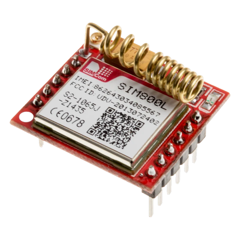
The SIM800L is SIMCom's quad-band GSM/GPRS modem: it runs from 3.4 V to 4.4 V (4.0 V recommended) and its supply must deliver bursts of up to 2 A (SIMCom SIM800L Hardware Design V1.00, p. 21). You talk to it with AT commands over a UART that autobauds from 1200 to 57600 bps, but its serial inputs top out at 2.8 V to 3.1 V (pp. 30, 58), so a resistor divider goes on its RXD even from a 3.3 V board. Power it from a Li-ion cell or a buck converter, never from a 5 V or 3.3 V board pin.
The SIM800L is a 2G cellular modem in a 15.8 × 17.8 mm package, sold to makers on a small red breakout with a micro SIM socket, an antenna pad and a u.FL connector, a status LED and two 6-pin headers. It covers GSM 850, EGSM 900, DCS 1800 and PCS 1900, transmitting at up to 2 W on the low bands (SIMCom Hardware Design V1.00, p. 11). With a SIM card and an antenna it can send and receive SMS, place voice calls through its MIC and SPK pins, and move data over GPRS.
Power is where most SIM800L projects fail. The module accepts 3.4 V to 4.4 V, and every GSM transmit burst pulls up to 2 A for a moment; if the supply sags below 3.0 V during a burst the module shuts itself down (pp. 21 to 22). That is why it resets as soon as it tries to register when fed through thin jumper wires or a weak regulator. A single 18650 cell or a buck converter set to about 4.0 V, with short thick wires and a large low-ESR capacitor, is the reliable choice.
The serial port runs at 2.8 V logic. Its inputs are specified to 2.8 V in the serial table and 3.1 V in the digital table (pp. 30, 58), and SIMCom's own reference circuits put a resistor network on the RXD line for 3.3 V and 5 V hosts (pp. 31 to 32). Its TXD output is high at 2.7 V to 2.8 V, which ESP32 and Pico read directly. Everything else is AT commands, which you can type through a serial bridge sketch or send from your code.
SIM800L pinout
| Pin | Function | Type |
|---|---|---|
| NET | Antenna pad | passive |
| VCC | Supply3.4 V to 4.4 V, 2 A peaks | power in |
| RST | Reset (active low)2.8 V | input |
| RXD | UART RX2.8 V logic | input |
| TXD | UART TX2.8 V logic | output |
| GND | Ground | power in |
| RING | Ring indicator | output |
| DTR | Sleep control | input |
| MICP | Microphone + | input |
| MICN | Microphone - | input |
| SPKP | Speaker + | output |
| SPKN | Speaker - | output |
How to wire the SIM800L
Pin by pin, for the board you have.
| SIM800L | Arduino Uno | Note |
|---|---|---|
| VCC | External 4.0 V supply + (18650 cell or buck converter, 2 A) | Put a 1000 µF low-ESR capacitor across VCC and GND at the module. |
| GND | GND (shared with the external supply) | |
| TXD | D2 (SoftwareSerial RX) | |
| RXD | D3 (SoftwareSerial TX) through a divider | 4.7 kΩ from D3 to RXD, 5.6 kΩ from RXD to GND: 5 V becomes about 2.7 V. |
- Do not power the module from the Uno's 5V pin (over its 4.5 V absolute maximum) or its 3.3V pin (below the 3.4 V minimum and far short of 2 A).
- The module's TXD is high at about 2.8 V, under the 3.0 V the ATmega328P guarantees as HIGH at 5 V (0.6 × VCC). It usually works; for a dependable link, buffer TXD with a 74HCT125 powered from 5 V.
| SIM800L | ESP32 DevKit V1 | Note |
|---|---|---|
| VCC | External 4.0 V supply + (18650 cell or buck converter, 2 A) | 1000 µF low-ESR capacitor across VCC and GND at the module. |
| GND | GND (shared with the external supply) | |
| TXD | GPIO16 (RX2) | |
| RXD | GPIO17 (TX2) through a divider | 2.2 kΩ from GPIO17 to RXD, 10 kΩ from RXD to GND: 3.3 V becomes about 2.7 V. |
- The ESP32's 3V3 pin cannot feed the modem: the voltage is below its 3.4 V minimum and the bursts reach 2 A.
- The 3.3 V TX line exceeds the module's 2.8 V serial input maximum without the divider.
| SIM800L | Raspberry Pi Pico | Note |
|---|---|---|
| VCC | External 4.0 V supply + (18650 cell or buck converter, 2 A) | 1000 µF low-ESR capacitor across VCC and GND at the module. |
| GND | GND (shared with the external supply) | |
| TXD | GP1 (Serial1 RX) | |
| RXD | GP0 (Serial1 TX) through a divider | 2.2 kΩ from GP0 to RXD, 10 kΩ from RXD to GND: 3.3 V becomes about 2.7 V. |
- Never feed VCC from VBUS (5 V) or 3V3(OUT) (too low and limited to about 300 mA); use its own supply with a shared ground.
SIM800L code
Every example here compiles for its board.
// SIM800L on Arduino Uno: wiring and a free simulation at https://www.tinkered.ai/components/sim800l
// SIM800L on an Arduino Uno: module TXD -> D2, module RXD <- D3 (through a 4.7k/5.6k divider)
#include <SoftwareSerial.h>

SoftwareSerial sim800(2, 3); // RX, TX

void sendAT(const char *cmd, unsigned long waitMs) {
  sim800.println(cmd);
  unsigned long start = millis();
  while (millis() - start < waitMs) {
    while (sim800.available()) Serial.write(sim800.read());
  }
  Serial.println();
}

void setup() {
  Serial.begin(115200);
  sim800.begin(9600);
  delay(3000); // give the modem time to boot
  Serial.println(F("SIM800L check"));
  for (int i = 0; i < 3; i++) sendAT("AT", 500); // lets autobauding lock on to 9600
  sendAT("ATI", 500);      // module name and firmware
  sendAT("AT+CSQ", 500);   // signal quality: 0 to 31, 99 = unknown
  sendAT("AT+CCID", 500);  // SIM card ID
  sendAT("AT+CREG?", 500); // ,1 = registered, ,5 = roaming
  Serial.println(F("Type AT commands (set line ending to Both NL & CR)."));
}

void loop() {
  while (Serial.available()) sim800.write(Serial.read());
  while (sim800.available()) Serial.write(sim800.read());
}
// SIM800L on ESP32 DevKit V1: wiring and a free simulation at https://www.tinkered.ai/components/sim800l
// SIM800L on an ESP32 DevKit V1: module TXD -> GPIO16, module RXD <- GPIO17 (through a 2.2k/10k divider)
#include <Arduino.h>

const int SIM_RX = 16; // ESP32 receives on GPIO16
const int SIM_TX = 17; // ESP32 transmits on GPIO17

void sendAT(const char *cmd, unsigned long waitMs) {
  Serial2.println(cmd);
  unsigned long start = millis();
  while (millis() - start < waitMs) {
    while (Serial2.available()) Serial.write(Serial2.read());
  }
  Serial.println();
}

void setup() {
  Serial.begin(115200);
  Serial2.begin(9600, SERIAL_8N1, SIM_RX, SIM_TX);
  delay(3000); // give the modem time to boot
  Serial.println("SIM800L check");
  for (int i = 0; i < 3; i++) sendAT("AT", 500); // lets autobauding lock on to 9600
  sendAT("ATI", 500);
  sendAT("AT+CSQ", 500);   // signal quality: 0 to 31, 99 = unknown
  sendAT("AT+CCID", 500);  // SIM card ID
  sendAT("AT+CREG?", 500); // ,1 = registered, ,5 = roaming
  Serial.println("Type AT commands (set line ending to Both NL & CR).");
}

void loop() {
  while (Serial.available()) Serial2.write(Serial.read());
  while (Serial2.available()) Serial.write(Serial2.read());
}
// SIM800L on Raspberry Pi Pico: wiring and a free simulation at https://www.tinkered.ai/components/sim800l
// SIM800L on a Raspberry Pi Pico (arduino-pico): module TXD -> GP1, module RXD <- GP0 (through a 2.2k/10k divider)
#include <Arduino.h>

void sendAT(const char *cmd, unsigned long waitMs) {
  Serial1.println(cmd);
  unsigned long start = millis();
  while (millis() - start < waitMs) {
    while (Serial1.available()) Serial.write(Serial1.read());
  }
  Serial.println();
}

void setup() {
  Serial.begin(115200);
  Serial1.setTX(0);
  Serial1.setRX(1);
  Serial1.begin(9600);
  delay(3000); // give the modem time to boot
  Serial.println("SIM800L check");
  for (int i = 0; i < 3; i++) sendAT("AT", 500); // lets autobauding lock on to 9600
  sendAT("ATI", 500);
  sendAT("AT+CSQ", 500);   // signal quality: 0 to 31, 99 = unknown
  sendAT("AT+CCID", 500);  // SIM card ID
  sendAT("AT+CREG?", 500); // ,1 = registered, ,5 = roaming
  Serial.println("Type AT commands (set line ending to Both NL & CR).");
}

void loop() {
  while (Serial.available()) Serial1.write(Serial.read());
  while (Serial1.available()) Serial.write(Serial1.read());
}
Before you wire it
- Feed VCC from a source that holds 3.4 V to 4.4 V while delivering 2 A bursts: a Li-ion cell or a buck converter set to about 4.0 V (SIMCom Hardware Design V1.00, p. 21).
- Put a large low-ESR capacitor across VCC and GND right at the module; SIMCom recommends at least 100 µF (p. 21) and makers commonly add 1000 µF.
- Divide the host's TX down before it reaches RXD: the serial inputs are specified to 2.8 V (Table 9, p. 30).
- Share ground between the modem's supply and the microcontroller.
- Attach the antenna before powering up and use a SIM on a network that still runs 2G.
- Never connect VCC to 5 V: the absolute maximum is 4.5 V (Table 41, p. 58).
- Never power it from a board's 3.3 V pin: that is under the 3.4 V minimum and cannot supply 2 A.
- Never run the supply through long thin jumper wires: below 3.0 V during a burst the module shuts down (p. 22).
- SIMCom asks for VBAT traces at least 60 mil wide for the transmit bursts (p. 22); on a breadboard, use short, thick wires from the supply straight to VCC and GND.
- The module reports UNDER-VOLTAGE WARNNING at 3.5 V or less and powers down below 3.4 V; it warns again at 4.3 V and shuts down above 4.4 V (p. 25), so watch for those messages on Serial when debugging resets.
- Autobauding is the default: send AT a few times after power-up so the module locks to your baud rate (p. 30). AT+IPR=9600 then AT&W fixes the rate if you need the RDY message at boot.
- The NET LED tells you its state without any code: a fast blink every 0.8 s means it is still searching, a slow blink every 3 s means it is registered (Table 34, p. 50).
- A 1N4007 dropping a 5 V supply to about 4.3 V is a popular hack, but it sits at the top of the range and sags under load; a buck converter set to 4.0 V is the safer way to run from 5 V or 12 V.
Specifications
- Supply voltage (VCC)
- 3.4 V to 4.4 V, 4.0 V recommendedSIMCom SIM800L Hardware Design V1.00, p. 21 and Table 42, p. 58
- Absolute maximum supply
- 4.5 V on VBATSIMCom SIM800L Hardware Design V1.00, Table 41, p. 58
- Peak current
- Up to 2 A during transmit bursts; supply must not drop below 3.0 VSIMCom SIM800L Hardware Design V1.00, pp. 21 to 22
- Average current
- 18.7 mA idle, 1.02 mA in sleep (BS-PA-MFRMS=9), about 200 mA in a GSM850 voice callSIMCom SIM800L Hardware Design V1.00, Table 48, p. 60
- Serial input levels
- VIH 2.5 V to 2.8 V, VIL up to 0.3 V; outputs VOH 2.7 V to 2.8 VSIMCom SIM800L Hardware Design V1.00, Table 9, p. 30
- Baud rate
- 1200 to 115200 bps; autobauding (default) from 1200 to 57600 bpsSIMCom SIM800L Hardware Design V1.00, p. 30
- Bands and power
- Quad band GSM 850/900/1800/1900; Class 4 (2 W) at 850/900 MHz, Class 1 (1 W) at 1800/1900 MHzSIMCom SIM800L Hardware Design V1.00, Table 1, p. 11
- Network LED (NET)
- 64 ms on / 800 ms off: searching; 64 ms on / 3000 ms off: registered; 64 ms on / 300 ms off: GPRS connectedSIMCom SIM800L Hardware Design V1.00, Table 34, p. 50
- Operating temperature
- -40 °C to +85 °CSIMCom SIM800L Hardware Design V1.00, Table 1, p. 11
From the SIMCom SIM800L product page and downloads, published by SIMCom Wireless Solutions.
Common mistakes
Powering it from the board's 5V or 3.3V pin
5 V is over the 4.5 V absolute maximum, and 3.3 V is under the 3.4 V minimum and cannot deliver 2 A peaks (SIMCom Hardware Design V1.00, pp. 21, 58). The symptom is a module that blinks a few times and resets, or a fried modem. Give it its own 4.0 V supply with a shared ground.
Resetting every time it tries to register
If the NET LED blinks, then the module restarts in a loop, the supply is sagging under the 2 A transmit bursts. Below 3.0 V the SIM800L shuts down (p. 22). Shorter, thicker wires, a stronger supply and a 1000 µF capacitor at VCC fix it.
Driving RXD straight from a 3.3 V or 5 V pin
The serial inputs are specified to 2.8 V (Table 9, p. 30), and SIMCom's reference designs put a resistor network on RXD for both 3.3 V and 5 V hosts (pp. 31 to 32). A simple divider to about 2.7 V does the job.
Using it where 2G is switched off
The SIM800L is GSM/GPRS only. In countries and on carriers that have retired their 2G networks it will never register, whatever the wiring. Check your carrier's 2G status before buying, or choose an LTE Cat-M or 4G module.
SIM800L questions
What power supply does the SIM800L need?
3.4 V to 4.4 V, ideally 4.0 V, from a source that can supply up to 2 A in short bursts (SIMCom SIM800L Hardware Design V1.00, p. 21). A single Li-ion or LiPo cell is a natural fit, or a buck converter set to 4.0 V. Add a large low-ESR capacitor at the module.
Can I connect the SIM800L to a 5 V Arduino?
Only its signals, and with care: power it from its own 3.4 V to 4.4 V supply, put a divider on the Arduino's TX into the module's RXD, and share ground. The module's 2.8 V TXD usually reads as HIGH on a 5 V Uno, though it is below the ATmega328P's guaranteed level, so a 74HCT125 buffer makes it dependable.
Why does my SIM800L keep restarting?
Almost always the supply: each transmit burst draws up to 2 A, and if the voltage drops below 3.0 V the module powers down (p. 22). Use a stronger supply, short thick wires and a 1000 µF capacitor across VCC and GND.
What baud rate does the SIM800L use?
It autobauds by default, between 1200 and 57600 bps, and supports fixed rates up to 115200 bps (p. 30). Open it at 9600, send AT a few times until it answers OK, and it stays at that rate until power is removed.
What do the NET LED blink patterns mean?
A 64 ms flash every 800 ms means it is searching for a network, every 3 s means it is registered, and every 300 ms means a GPRS connection is up (Table 34, p. 50). If it never slows down, check the antenna, the SIM and that 2G is still available.
Does the SIM800L work with 4G SIM cards?
A 4G-era SIM card works if the carrier still runs a 2G (GSM) network, because the modem only speaks GSM/GPRS on 850, 900, 1800 and 1900 MHz (Table 1, p. 11). Where 2G has been shut down it cannot register on any card.
Build something with the SIM800L
- Build this
SMS GPS tracker
Reply to any incoming text with a Google Maps link to the current position.
- Build this
Text-controlled relay
Turn a pump or a light on and off by sending ON or OFF from your phone.
This page as plain Markdown, for ChatGPT, Claude or your own agent. /components/sim800l.md