NEO-6M GPS Module (GY-NEO6MV2)
The GY-NEO6MV2 board carries u-blox's NEO-6M GPS receiver, a regulator and a patch antenna, and streams NMEA position sentences at 9600 baud.
- Receiver50 channels, GPS L1 C/A, u-blox 6 engine
- Time to first fix (NEO-6M)27 s cold, 27 s warm, 1 s hot, under 3 s aided
- Sensitivity (NEO-6M)-161 dBm tracking, -147 dBm cold start
- Horizontal accuracy2.5 m (GPS), 2.0 m (SBAS)
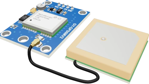
The NEO-6M is a 50-channel u-blox 6 GPS receiver with 2.5 m horizontal accuracy and a 27 s cold-start fix, which outputs NMEA sentences on its UART at 9600 baud 8N1 by default (u-blox NEO-6 datasheet GPS.G6-HW-09005-E, pp. 6, 22). On the GY-NEO6MV2 board, power VCC from 3.3 V or 5 V, wire the module's TX to the board's RX, and feed the board's TX to the module's RX through a 1 kΩ / 2 kΩ divider on a 5 V board, since the chip's inputs are rated to 3.6 V maximum (p. 14).
The NEO-6M is u-blox's 16 × 12.2 × 2.4 mm GPS module from the NEO-6 family (u-blox NEO-6 datasheet, p. 1). Its 50-channel u-blox 6 engine tracks the GPS L1 C/A signal and reaches a first fix in 27 s from a cold start and about 1 s from a hot start, with -161 dBm tracking sensitivity and 2.5 m horizontal accuracy (p. 6). It updates at up to 5 Hz and speaks NMEA 0183 version 2.3 as well as u-blox's binary UBX protocol (pp. 6, 9).
Makers rarely solder the bare module: they buy the GY-NEO6MV2 breakout, which adds a 3.3 V regulator so VCC takes 3.3 V to 5 V, a rechargeable backup cell and an EEPROM that keep the almanac and settings between power cycles, a red LED that blinks once a second when the receiver has a fix, and a ceramic patch antenna on a U.FL cable. Its 4-pin header is VCC, RX, TX and GND.
Out of the box the receiver sends GGA, GLL, GSA, GSV, RMC, VTG and TXT sentences once a second at 9600 baud, 8 data bits, no parity, 1 stop bit (datasheet, p. 22). A library such as TinyGPS++ parses them into latitude, longitude, altitude, speed and time. The NEO-6M chip itself runs at 2.7 V to 3.6 V and draws about 47 mA while acquiring and 39 mA while tracking (p. 15), so the board's 3.3 V logic UART needs a divider on its RX line when driven by a 5 V Arduino.
NEO-6M GPS Module (GY-NEO6MV2) pinout
| Pin | Function | Type |
|---|---|---|
| VCC | VCC: 3.3-5 V (into the board's MIC5205 3.3 V regulator)3.3–5 V | power in |
| RX | UART module RX: connect to the board's TX (divide a 5V TX down to 3.3V) | input |
| TX | UART module TX: connect to the board's RX3.3 V | output |
| GND | GND | power in |
How to wire the NEO-6M GPS Module (GY-NEO6MV2)
Pin by pin, for the board you have.
| NEO-6M GPS Module (GY-NEO6MV2) | Arduino Uno | Note |
|---|---|---|
| VCC | 5V | |
| GND | GND | |
| TX | D4 | |
| RX | D3 | through a 1 kΩ resistor, with a 2 kΩ resistor from RX to GND (a divider) |
| NEO-6M GPS Module (GY-NEO6MV2) | ESP32 DevKit V1 | Note |
|---|---|---|
| VCC | 3V3 | |
| GND | GND | |
| TX | GPIO13 (D13) | |
| RX | GPIO14 (D14) | direct: the board's 3.3 V signal needs no divider |
| NEO-6M GPS Module (GY-NEO6MV2) | Raspberry Pi Pico | Note |
|---|---|---|
| VCC | 3V3 | |
| GND | GND | |
| TX | GP0 | |
| RX | GP1 | direct: the board's 3.3 V signal needs no divider |
NEO-6M GPS Module (GY-NEO6MV2) code
Every example here compiles for its board.
// NEO-6M GPS Module (GY-NEO6MV2) on Arduino Uno: wiring and a free simulation at https://www.tinkered.ai/components/gps-neo6m
#include <SoftwareSerial.h>
#include <TinyGPS++.h>

SoftwareSerial gpsSerial(4, 3);  // RX, TX: the module's TX, RX (through the divider)
TinyGPSPlus gps;
unsigned long lastWait = 0;

void setup() {
  Serial.begin(115200);
  gpsSerial.begin(9600);         // the NEO-6M's speed out of the box
  Serial.println("GPS starting (a cold start takes about 30 s)");
}

void loop() {
  while (gpsSerial.available()) gps.encode(gpsSerial.read());

  if (gps.location.isUpdated()) {
    Serial.print("lat ");  Serial.print(gps.location.lat(), 6);
    Serial.print(" lon "); Serial.print(gps.location.lng(), 6);
    Serial.print(" sats "); Serial.print(gps.satellites.value());
    Serial.print(" alt "); Serial.print(gps.altitude.meters());
    Serial.print(" km/h "); Serial.println(gps.speed.kmph());
  }
  if (!gps.location.isValid() && millis() - lastWait > 2000) {
    lastWait = millis();
    Serial.print("waiting for fix, satellites in view: ");
    Serial.println(gps.satellites.value());
  }
}
Before you wire it
- Cross the UART: module TX → board RX, module RX → board TX.
- On a 5V board (Uno, Nano, Mega) put a divider into the module's RX: 1k from the board's TX to RX, 2k from RX to GND. The module's RX is optional when the sketch only reads (TinyGPS++), but it is needed to configure it.
- Use TinyGPS++ (#include <TinyGPS++.h>) and feed it every byte: while (gps_serial.available()) gps.encode(gps_serial.read()); in loop(), no long delay() (SoftwareSerial holds 64 bytes; a second of NMEA is ~500).
- Print "waiting for fix" until gps.location.isValid(); never treat 0,0 or an old value as a position. Check gps.location.isUpdated() for new ones.
- No TX to TX or RX to RX.
- No module RX straight onto a 5V board's TX: the divider is part of the build.
- No Serial for the GPS on an Uno or Nano while also printing to the monitor.
- No ESP8266 GPIO2 (D4) for the module's TX: it is Serial1, which only transmits.
- No SparkFun u-blox GNSS library on a NEO-6M: it needs UBX-NAV-PVT, which u-blox 6 does not have (it times out). NO Adafruit_GPS commands: they are MediaTek PMTK ("NMEA unknown msg" on a u-blox).
- No breadboard holes: list it by type, placement is automatic.
- Power the GY-NEO6MV2 board's VCC from 3.3 V or 5 V; its regulator feeds the NEO-6M chip, which itself takes 2.7 V to 3.6 V (u-blox datasheet, p. 15). Budget at least 67 mA for the chip's peak (p. 15).
- Cross the UART: module TX to the board's RX, board's TX to module RX. The board has no level shifter, and the chip's input pins are rated to 3.6 V maximum (p. 14), so on a 5 V Arduino put a 1 kΩ / 2 kΩ divider into the module's RX. On an ESP32 or Pico wire it directly.
- The module's RX is only needed to send configuration commands (UBX or NMEA); a sketch that only reads positions can leave it unconnected.
- On an Uno or Nano read the GPS on SoftwareSerial (for example D4 RX, D3 TX) so D0 and D1 stay free for the Serial Monitor; on a Mega, ESP32 or Pico use a hardware UART such as Serial1 or Serial2.
- Feed the parser every byte as it arrives: six or more NMEA sentences arrive each second (u-blox datasheet, p. 22), far more than SoftwareSerial's 64-byte buffer holds, so avoid long delay() calls in loop().
- Give the patch antenna a view of the sky with its ceramic face up. Indoors, a fix is slow or never comes.
- The NEO-6 chip itself takes 2.7 to 3.6 V; 3.3 to 5 V is the board's input, through its regulator.
Specifications
- Receiver
- 50 channels, GPS L1 C/A, u-blox 6 engineu-blox NEO-6 datasheet GPS.G6-HW-09005-E, p. 6
- Time to first fix (NEO-6M)
- 27 s cold, 27 s warm, 1 s hot, under 3 s aidedu-blox NEO-6 datasheet GPS.G6-HW-09005-E, p. 6
- Sensitivity (NEO-6M)
- -161 dBm tracking, -147 dBm cold startu-blox NEO-6 datasheet GPS.G6-HW-09005-E, p. 6
- Horizontal accuracy
- 2.5 m (GPS), 2.0 m (SBAS)u-blox NEO-6 datasheet GPS.G6-HW-09005-E, p. 6
- Max update rate (NEO-6M)
- 5 Hzu-blox NEO-6 datasheet GPS.G6-HW-09005-E, p. 6
- Chip supply (NEO-6M)
- 2.7 V to 3.6 V, 3.0 V typical; 3.6 V absolute maximumu-blox NEO-6 datasheet GPS.G6-HW-09005-E, pp. 14, 15
- Chip current at 3.0 V
- 47 mA acquisition, 39 mA tracking, 11 mA power save; 67 mA peaku-blox NEO-6 datasheet GPS.G6-HW-09005-E, p. 15
- UART default
- 9600 baud, 8N1; GGA, GLL, GSA, GSV, RMC, VTG, TXTu-blox NEO-6 datasheet GPS.G6-HW-09005-E, p. 22
- Input pin voltage
- 3.6 V absolute maximumu-blox NEO-6 datasheet GPS.G6-HW-09005-E, p. 14
- Operating temperature
- -40 °C to 85 °Cu-blox NEO-6 datasheet GPS.G6-HW-09005-E, p. 15
- Supply voltage
- 3.3–5 V
- Maximum supply voltage
- 5.5 V
- Interface
- UART
- Dimensions
- 54.93 × 39.3 × 12.5 mm
- Weight
- 12 g
From the u-blox NEO-6M (generic GY-NEO6MV2 module)'s datasheet, published by u-blox NEO-6M (generic GY-NEO6MV2 module).
Common mistakes
Testing indoors and waiting for a fix
The NEO-6M needs 27 s for a cold-start fix even under open sky (u-blox datasheet, p. 6), and walls and roofs can block the signal entirely. Take it outside or to a window; the board's LED starts blinking once a fix is found.
Driving the module's RX with 5 V
The NEO-6M's input pins are rated to 3.6 V absolute maximum (p. 14) and the GY-NEO6MV2 board has no level shifter. Use a 1 kΩ / 2 kΩ divider from a 5 V board's TX.
Swapping TX and RX
TX goes to the board's RX and RX to the board's TX. Wired TX to TX the sketch receives nothing and the Serial Monitor stays blank.
Treating 0,0 as a position
Until the receiver has a fix, the parser holds no valid location. Check gps.location.isValid() in TinyGPS++ before using the coordinates, and print "waiting for fix" until then.
Wrong baud rate
The UART defaults to 9600 baud, 8N1 (u-blox datasheet, p. 22). Opening the port at another speed shows garbage characters instead of $GPGGA and $GPRMC lines.
NEO-6M GPS Module (GY-NEO6MV2) questions
How do I connect a NEO-6M GPS to an Arduino Uno?
VCC to 5V, GND to GND, module TX to D4 and D3 to module RX through a 1 kΩ / 2 kΩ divider, then SoftwareSerial gps(4, 3) and gps.begin(9600), the receiver's default speed (u-blox NEO-6 datasheet, p. 22). Pass every byte to TinyGPS++ with gps.encode() and read gps.location once it is valid.
Can I use the NEO-6M with an ESP32 or Raspberry Pi Pico at 3.3 V?
Yes. Power the GY-NEO6MV2 board from 3.3 V and connect TX and RX directly: the chip runs at 2.7 V to 3.6 V and its inputs take up to 3.6 V (u-blox datasheet, pp. 14, 15), so 3.3 V logic needs no divider. On an ESP32 use Serial2.begin(9600, SERIAL_8N1, rxPin, txPin).
How long does the NEO-6M take to get a fix?
About 27 s from a cold or warm start and about 1 s from a hot start, under open sky (u-blox NEO-6 datasheet, p. 6). The board's backup cell keeps satellite data between power cycles, which is what makes hot starts possible.
Why does my NEO-6M show no data or no fix?
If no characters arrive, check that TX goes to the board's RX and the port is at 9600 baud (u-blox datasheet, p. 22). If sentences arrive but the position fields are empty, the receiver has no fix yet: move it outdoors with the antenna facing the sky and wait at least the 27 s cold-start time (p. 6).
How accurate is the NEO-6M?
u-blox specifies 2.5 m horizontal accuracy with GPS alone and 2.0 m with SBAS, plus 0.1 m/s velocity accuracy (NEO-6 datasheet, p. 6), measured under good signal conditions.
Can the NEO-6M update faster than once a second?
Yes, up to 5 Hz (u-blox NEO-6 datasheet, p. 6), set with the UBX CFG-RATE message. Raise the baud rate too, since five sets of sentences a second do not fit comfortably in 9600 baud.
Build something with the NEO-6M GPS Module (GY-NEO6MV2)
- Build this
GPS tracker
Log positions to a microSD card or send them over LoRa or Wi-Fi to map a bike ride or a vehicle.
- Build this
GPS speedometer
Show speed, heading and altitude on an OLED or LCD from the RMC and GGA sentences.
- Build this
Accurate clock
Set a display clock or an RTC from GPS time, with no network needed.
- Build this
Geofence alarm
Sound a buzzer or send a message when the device leaves a set area.
This page as plain Markdown, for ChatGPT, Claude or your own agent. /components/gps-neo6m.md